A sawing host of a pipe multi-head sawing machine

A sawing machine and sawing technology, applied in metal sawing equipment, sawing machine devices, metal processing equipment and other directions, can solve the problems of low sawing efficiency, high equipment investment cost and high cost, so as to improve the sawing efficiency and shorten the The effect of sawing time

Active Publication Date: 2018-09-11
SUZHOU KINKALTECK MACHINERY TECH
View PDF7 Cites 0 Cited by
  • Summary
  • Abstract
  • Description
  • Claims
  • Application Information

AI Technical Summary

Problems solved by technology

[0002] The sawing principle of the current multi-head sawing machine is the same as that of the single-head sawing machine, which is to combine multiple sawing heads on one device, and use the clamping device to correspond to the sawing machine head one by one. After the clamping device clamps the pipe , and then use the saw blade of the saw head to saw the pipe, but this multi-head sawing machine has the following disadvantages: 1. The sawing efficiency is low, and it needs to be loaded, fed, and clamped by the clamping device, and then the saw blade The feeding, retracting, loosening of the clamping device, and discharging these actions, so sawing a pipe takes a long time and the efficiency is very low; 2. The cost of this sawing machine is high, due to the Each step requires a corresponding device or mechanism to realize the action. Therefore, the equipment investment cost is high and the volume is large; 3. Since this multi-head sawing machine first needs to be clamped by the clamping mechanism when sawing, the shortest time for sawing the pipe is The distance cannot be made shorter due to the influence of the clamping mechanism. The clamping mechanism limits the shortest limit length of the pipe cut by the multi-head saw

Method used


Image

  • A sawing host of a pipe multi-head sawing machine
  • A sawing host of a pipe multi-head sawing machine
  • A sawing host of a pipe multi-head sawing machine

Examples


Embodiment Construction

[0029] The present invention will be further described in detail below through specific embodiments.

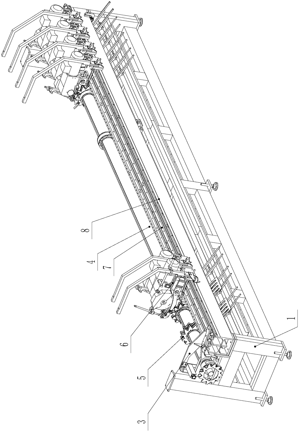
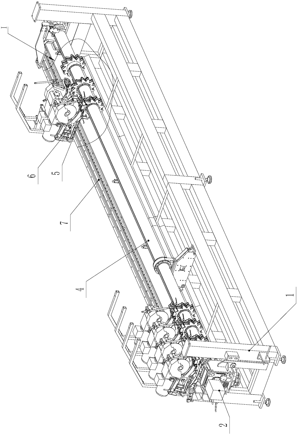
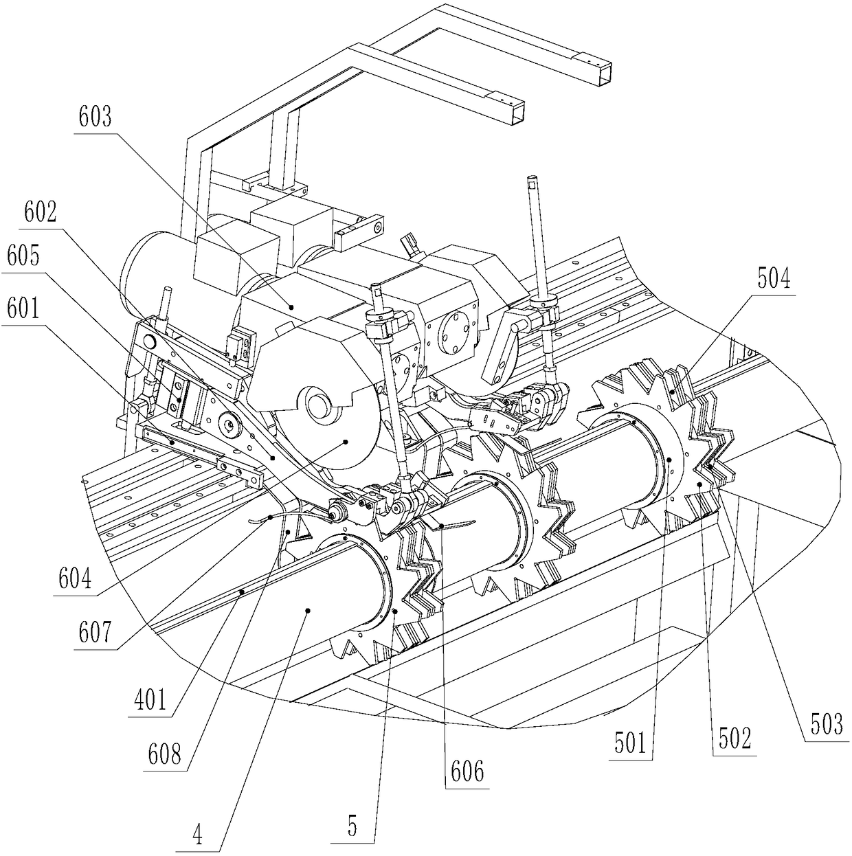
[0030] Such as Figure 1 to Figure 5 As shown, a sawing host of a pipe multi-head sawing machine includes a frame 1 on which a plurality of sawing heads 6 are installed, and the sawing head 6 includes a base installed on the frame 1 601. A bracket 602 is installed on the base 601, a power box 603 is installed on the bracket 602, and the saw blade 604 is installed on the output shaft of the power box 603. The position of the shifting gear set 5 on the feed spindle 4 corresponds to the position of the shifting gear set 5, which is provided with a feed gap 504 that is convenient for the saw blade 604 to enter, and the depth of the feed gap 504 is greater than the pipe diameter of the pipe; The length of the saw blade 604 extending into the knife feed gap 504 is greater than the pipe diameter of the pipe, and the base 601 is provided with a pressing device for pressing the pipe dra...


PUM


Abstract

The invention discloses a saw-cutting mainframe of a multi-head saw-cutting machine for a tube. The saw-cutting mainframe comprises a rack, wherein a plurality of saw-cutting heads are installed on the rack, each saw-cutting head comprises a base installed on the rack, a support is installed on the base, a power box is installed on the support, a saw blade is installed on an output shaft of the power box, the position of the saw blade is corresponding to the position of a shifting gear group installed on a rotatable feeding spindle, a feeding gap for facilitating the saw blade to enter is arranged in the shifting gear group, and the depth of the feeding gap is greater than the tube diameter of the tube; and the length of each saw blade stretching in the corresponding feeding gap is greater than the tube diameter of the tube, and a compression device for compressing the tube shifted by the corresponding shifting gear group is arranged on the corresponding base. The saw-cutting mainframe is capable of carrying out rotary feeding saw-cutting by cooperating with the shifting gear groups, thus the saw-cutting efficiency is increased.

Description

Technical field [0001] The invention relates to a sawing host, in particular to a sawing host of a pipe multi-head sawing machine, which is used for correspondingly matching with a shifting gear set. Background technique [0002] The sawing principle of the current multi-head sawing machine is the same as that of single-head sawing, that is, multiple sawing heads are combined into one device, and the clamping device is one-to-one corresponding to the sawing head. After the clamping device clamps the pipe , And then use the saw blade of the sawing head to saw the pipe. However, this multi-head sawing machine has the following shortcomings: 1. The sawing efficiency is low, and the clamping action of the feeding, feeding and clamping device is required, and then the saw blade It takes a long time to cut a pipe, and the efficiency is very low; 2. The cost of this kind of sawing machine is high because of the high cost of the sawing machine. Each step requires a corresponding device ...

Claims


Application Information

Patent Timeline
Patent Type & Authority Patents(China)
IPC IPC(8): B23D45/10B23D47/04B23D45/12
CPCB23D45/10B23D45/12B23D47/04B23D47/045
Inventor 柯晓华
Owner SUZHOU KINKALTECK MACHINERY TECH
Why Eureka
Try Eureka