
A floating core bending mechanism and bending method

A floating die core and floating mechanism technology, applied in the field of sheet metal bending, can solve the problems of reducing production efficiency, reducing production output, difficult to accurately grasp the angle, etc., to improve bending efficiency, increase production output, and simple bending process Effect

Active Publication Date: 2018-07-17
CHENGDU HOMIN TECH
View PDF4 Cites 0 Cited by
  • Summary
  • Abstract
  • Description
  • Claims
  • Application Information

AI Technical Summary

Problems solved by technology

However, when the mold is to be opened to take out the finished product, because the barb 18 restricts the upward movement of the upper mold, the mold cannot be opened normally, so this bending or bending method cannot be popularized. The sheet metal method cannot realize continuous production of finished products, which reduces production efficiency and production output, and it is difficult to meet the characteristics of large market demand
In addition, through this bending method, the accuracy of the bending angle is poor, it is difficult to accurately grasp the angle, and the product quality is poor

Method used


Image

  • A floating core bending mechanism and bending method
  • A floating core bending mechanism and bending method
  • A floating core bending mechanism and bending method

Examples


Embodiment Construction

[0024] The present invention will be further described below in conjunction with accompanying drawing, protection scope of the present invention is not limited to the following:

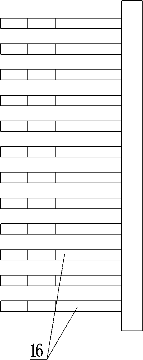
[0025] Such as Figure 4~8 As shown, a floating core bending mechanism includes a base 1, a floating core 2, a left force transmission column 3, a right force transmission column 4 and a connecting plate 5 arranged on the top of the base 1. The left force transmission Both the column 3 and the right force transmission column 4 are located directly above the connecting plate 5, and the bottoms of the left force transmission column 3 and the right force transmission column 4 are provided with threaded holes 6, and the width of the floating mold core 2 is the same as that of the sheet material 16 The widths are equal, the right end of the floating core 2 is fixed on the right force transmission column 4, the left end of the floating core 2 is located above the left force transmission column 3 and a hori...


PUM


Abstract

The invention discloses a floating mold core bending mechanism. The floating mold core bending mechanism comprises a base (1), a floating mold core (2), a left force transferring column (3), a right force transferring column (4) and a connecting plate (5) arranged at the top of the base (1). A fillet (7) is arranged on the left end face of the floating mold core (2). Springs (9) are fixed to the bottoms of cavities (11). Liner tubes (8) penetrate through the connecting plate (5) and communicate with the cavities (11). Threaded rods (10) are arranged inside the liner tubes (8), and the lower ends of the threaded rods (10) are fixed to the tops of the springs (9). The bending mechanism further comprises a female mold insert (12) arranged at the top of the connecting plate (5) and located at the left side of a left floating mechanism, and an arc-shaped groove (13) matched with the fillet (7) is formed in the upper right corner of the female mold insert (12). The arc-shaped groove (13) is formed under the fillet (7). The floating mold core bending mechanism has the beneficial effects that bending precision is high, the bending process is simple, continuous bending is realized, and bending efficiency is improved.

Description

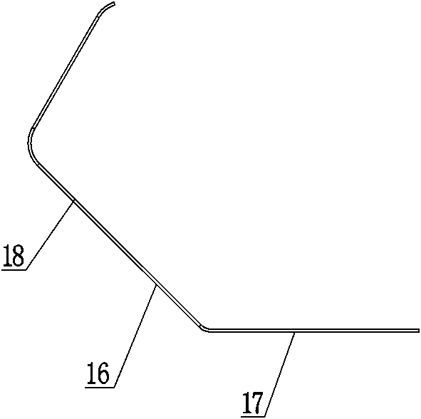
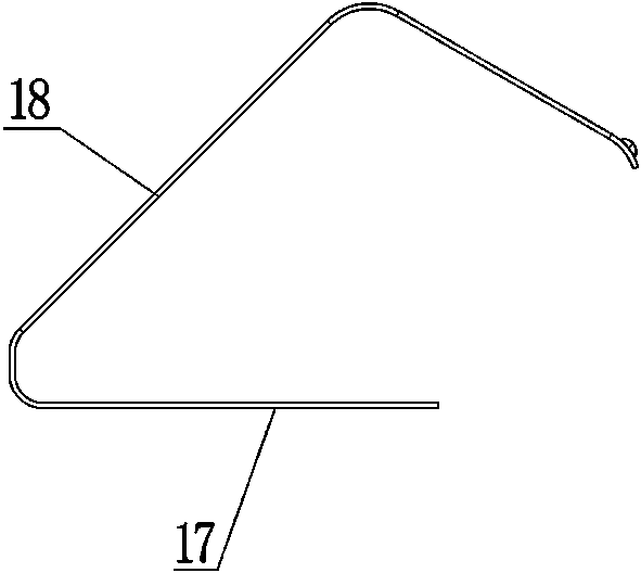
technical field [0001] The invention relates to the technical field of sheet material bending, in particular to a floating core bending mechanism and a bending method. Background technique [0002] In the electronic product production industry, sheets of various shapes are usually produced by bending, and the blanks are usually used such as figure 1 Shown sheet material 16, this sheet material 16 is made up of horizontal edge 17 and barb 18, and horizontal edge 17 is connected with barb 18, will bend this sheet material 16 into such as figure 2 When the finished product is shown, the finished product is obtained by bending the barb 18 of the sheet material 16 sequentially at a certain angle. Usually, the upper die is pressed on the horizontal edge 17 of the sheet material 16 from top to bottom, so that the barb 18 Flip to process the finished product. However, when the mold is to be opened to take out the finished product, because the barb 18 restricts the upward movement...

Claims


Application Information

Patent Timeline
Patent Type & Authority Patents(China)
IPC IPC(8): B21D37/10B21D5/00
CPCB21D5/00B21D37/10
Inventor 田国富王洪伟游健朱浔庄严王希亮
Owner CHENGDU HOMIN TECH
Learn More