
Contactless power supply system and vehicle power supply device

A technology of non-contact power supply and power supply system, which is applied to battery circuit devices, circuit devices, devices along the driving track, etc., and can solve problems such as large energy loss

Active Publication Date: 2016-11-23
IHI CORP
View PDF9 Cites 2 Cited by
  • Summary
  • Abstract
  • Description
  • Claims
  • Application Information

AI Technical Summary

Problems solved by technology

[0015] Therefore, the relative position between the primary coil for power feeding and the secondary coil for power feeding is shifted (the arrangement of the primary coil for power feeding and the secondary coil for power feeding is not the closest state, that is, the primary coil for power feeding and the secondary coil for power feeding If the shape of the secondary coil is the same shape, there is a reasonable limit in the state where the center of the primary coil for power feeding and the center of the secondary coil for power feeding are not aligned). big bad situation

Method used


Image

  • Contactless power supply system and vehicle power supply device
  • Contactless power supply system and vehicle power supply device
  • Contactless power supply system and vehicle power supply device

Examples


Embodiment Construction

[0072] Hereinafter, modes for implementing the present invention will be described with reference to the drawings.

[0073] First, a non-contact power supply system according to an embodiment of the present invention will be described based on the drawings.

[0074] First, the contactless power supply system 100 according to the first to second embodiments of the present invention will be described based on the drawings.

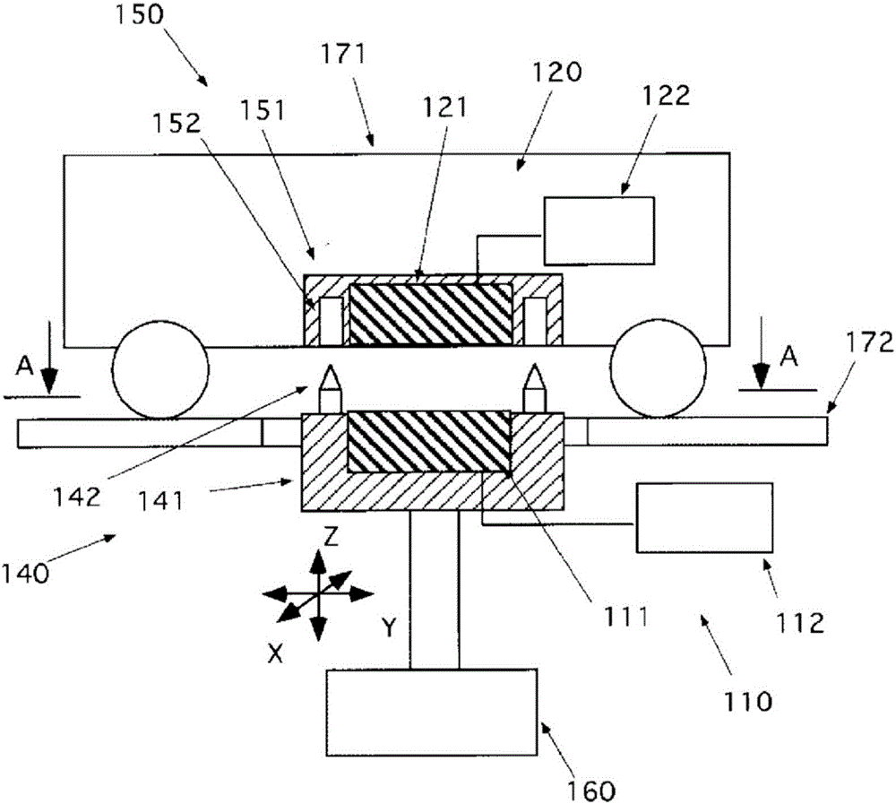
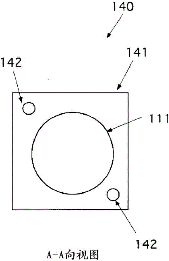
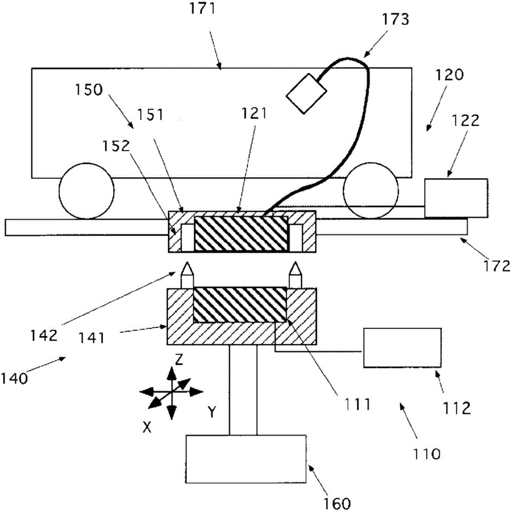
[0075] figure 1 It is a conceptual diagram of the contactless power supply system according to the first embodiment of the present invention. figure 2 It is an A-A arrow view of the contactless power supply system according to the first embodiment of the present invention. image 3 It is a conceptual diagram of a contactless power supply system according to a second embodiment of the present invention.

[0076]The contactless power supply system 100 according to the first to second embodiments of the present invention includes a power supply device 110 ...


PUM


Abstract

The present invention is a contactless power supply system intended to eliminate energy loss due to positional misalignment by supplying power contactlessly in a mated orientation. This contactless power supply system is provided with: a power reception device (120) having a power-supplying secondary coil (121); a power supply device (110) having a power-supplying primary coil (111) and a driving circuit (112); a primary coil support member (140) having mating members (142) that mate with mated members (152), the primary coil support member (140) supporting the power-supplying primary coil; a secondary coil support member (150) having the mated members that mate with the mating members, the secondary coil support member (150) supporting the power-supplying secondary coil; and an orientation / position adjustment mechanism (160) for changing orientation between an open orientation, which is where the mated members are released from the mating members, and a mating orientation, which is where the mating members are mated with the mated members.

Description

technical field [0001] The present disclosure relates to a contactless power supply system and a vehicle power supply device that supplies power to a vehicle capable of receiving power supply. This application claims the benefit of priority of Japanese Patent Application No. 2014-074261 filed on March 31, 2014, the entire contents of which are incorporated by reference. Background technique [0002] In recent years, vehicles driven by electricity are used. [0003] Therefore, it is necessary to supply power to the vehicle. [0004] For example, the power supply equipment is used to supply power to a parked vehicle. [0005] The power supply device can supply power to the vehicle through contactless. [0006] For example, a vehicle has a non-contact secondary coil for power feeding at the bottom of the vehicle, and a concept is being studied in which a primary coil for power feeding is provided under the vehicle to supply power to the vehicle. [0007] Figure 16 It is a ...

Claims


Application Information

Patent Timeline
IPC IPC(8): H02J50/12B60L5/00B60L11/18B60M7/00H02J7/00H02J50/00H02J50/10H02J50/90
CPCY02T90/12Y02T90/14B60L53/30B60L53/38B60L53/36B60L53/122B60L53/126H02J7/0042Y02T10/7072Y02T10/70H02J50/50H02J50/90H02J50/12H02J50/005E04H6/22H02J50/10
Inventor 高津裕二上田章雄德良晋桥爪祥阿久根圭林亨柴田翔平
Owner IHI CORP
Learn More