


Quick Research
Generate reliable direction feasibility study reports for your R&D in just a few steps.

Technical Q&A
Discover and master advanced knowledge NOW. Basics, ideas, possibilities, all at once.

Find Solutions
As an expert in R&D theories, this can generate solutions to your technical problems instantly.

Evaluate Feasibility
Analyze your overall solution with one click, know your potential R&D risks in advance.

Monitor Landscape
Get weekly tech updates, stay abreast of the latest tech innovations and key insights.
Photographing method and terminal
A technology of terminal and light intensity, applied in the parts and electrical components of TVs and color TVs, etc., can solve problems such as poor photo-taking effects and improper selection of light metering points, achieve good photo effects, and solve problems with poor photo-taking effects. Effect
- Summary
- Abstract
- Description
- Claims
- Application Information
AI Technical Summary
Problems solved by technology
Method used
Image

Examples
Embodiment 1
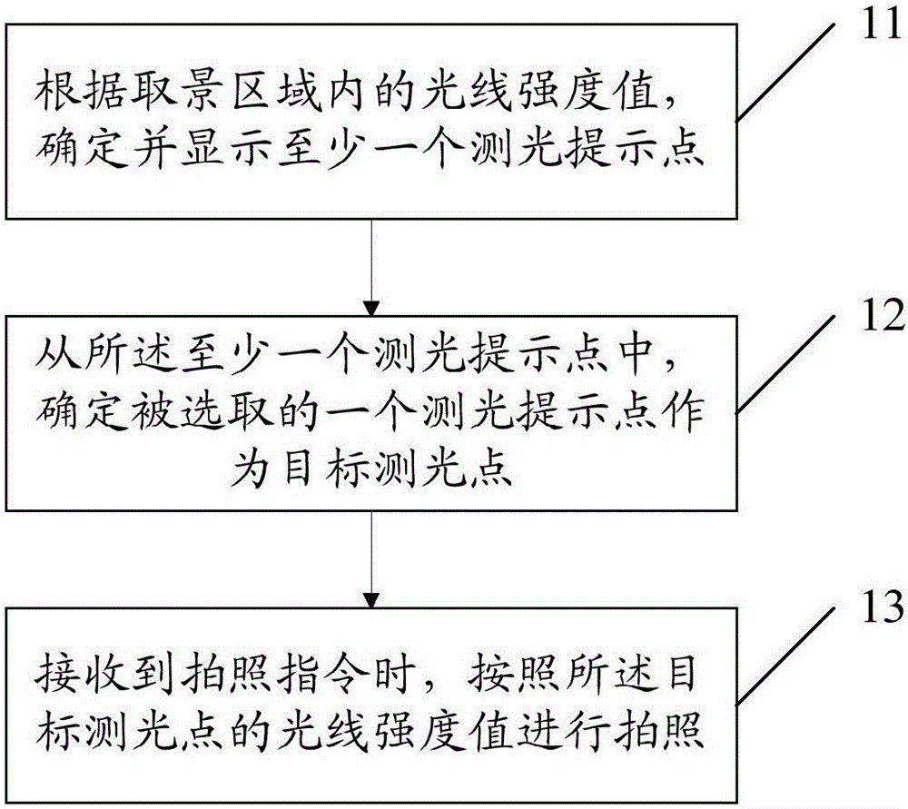
[0023] Such as figure 1 As shown, the photographing method provided by Embodiment 1 of the present invention includes:
[0024] Step 11: Determine and display at least one light metering prompt point according to the light intensity value in the viewing area.
[0025] That is, at least one light metering prompt point is extracted from the picture captured by the camera lens. The light metering prompt point prompts the user in a certain form. For example, a circular virtual frame, a flashing virtual frame, and the like.
[0026] Step 12: From the at least one light metering prompt point, determine a selected light metering prompt point as a target light metering point.
[0027] That is, the selected light metering prompt point is used as the target light metering point. After the camera lens is activated, the system will automatically select a light metering point, or the user selects a light metering prompt point from multiple light metering prompt points as the target lig...
Embodiment 2
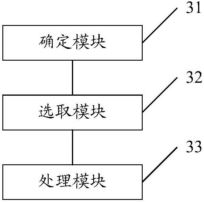
[0066] Such as image 3 As shown, the terminal provided in Embodiment 2 of the present invention includes:
[0067] The determination module 31 is configured to determine and display at least one light metering prompt point according to the light intensity value in the viewing area.
[0068] That is, at least one light metering prompt point is extracted from the picture captured by the camera lens.
[0069] The selection module 32 is configured to determine a selected photometric prompt point from at least one photometric prompt point as a target photometric point.
[0070] That is, the selected light metering prompt point is used as the target light metering point. The processing module 33 is configured to take a picture according to the light intensity value of the target photometry point when receiving the picture taking instruction.
[0071] Specifically, according to the light intensity value of the target photometering point, determine the brightness and darkness of t...
Embodiment 3
[0085] Such as Figure 4 As shown, the terminal 400 provided in Embodiment 3 of the present invention includes:
[0086] At least one processor 401 , memory 402 , at least one network interface 404 and other user interface 403 . Various components in the terminal 400 are coupled together through a bus system 405 . It can be understood that the bus system 405 is used to realize connection and communication between these components. In addition to the data bus, the bus system 405 also includes a power bus, a control bus and a status signal bus. But for clarity, in Figure 4 The various buses are denoted bus system 405 in FIG.
[0087] Wherein, the user interface 403 may include a display, a keyboard or a pointing device (for example, a mouse, a trackball (trackball), a touch panel or a touch screen, and the like.
[0088] It can be understood that the memory 402 in the embodiment of the present invention may be a volatile memory or a non-volatile memory, or may include both...
PUM
 Abstract
Description
Claims
Application Information
 - R&D Engineer
- R&D Manager
- IP Professional
- Industry Leading Data Capabilities
- Powerful AI technology
- Patent DNA Extraction
Browse by: Latest US Patents, China's latest patents, Technical Efficacy Thesaurus, Application Domain, Technology Topic, Popular Technical Reports.
© 2024 PatSnap. All rights reserved.Legal|Privacy policy|Modern Slavery Act Transparency Statement|Sitemap|About US| Contact US: help@patsnap.com