
Platform type charging system

A charging system and station-type technology, applied in the field of electric vehicle charging stations, can solve the problems of development restrictions, low output power, and high operating costs, and achieve the effects of resource sharing, short charging time, and low construction costs

Active Publication Date: 2016-11-23
谢镕安
View PDF4 Cites 2 Cited by
  • Summary
  • Abstract
  • Description
  • Claims
  • Application Information

AI Technical Summary

Problems solved by technology

[0003] The development of charging facilities, because it involves urban planning, construction land, reconstruction of buildings and distribution networks, sharing of charging station resources, investment and operation models, etc., there are many stakeholders and it is difficult to promote, especially the construction of traditional charging infrastructure requires land acquisition and demolition , due to the high cost of demolition and expensive urban land, its development is subject to certain restrictions
In the prior art, since the output of the AC charging station is alternating current, and then the charging gun of the charging station supplies power to the on-board charger on the electric vehicle for charging, the work efficiency of the on-board charger is relatively low, and the output power is small, so the charging time Longer, generally takes 5-8 hours; on the other hand, due to the unsolved problem of charging metering and charging, multiple operating units cannot share charging station resources, resulting in high operating costs; in addition, the on-board power management system (BMS) cannot communicate with the charger Communication (handshake), so it is not possible to perform intelligent charging control on high-power intelligent chargers
The above reasons hinder the popularization and application of electric vehicles

Method used


Image

  • Platform type charging system
  • Platform type charging system
  • Platform type charging system

Examples


Embodiment Construction

[0018] The specific implementation manners of the present invention will be further described in detail below in conjunction with the accompanying drawings.

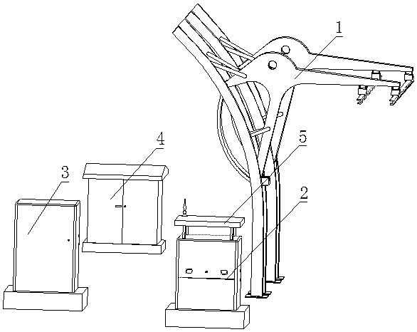
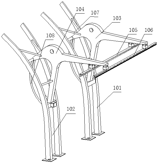
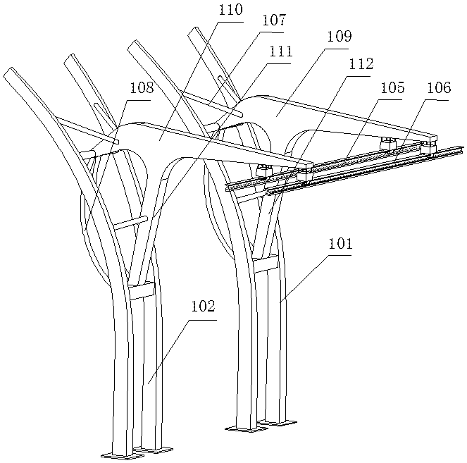
[0019] Such as figure 1 and figure 2 The shown platform charging system includes a charging system 2 that supplies power to the power supply system 1; a power transformation system 4 that supplies power to the charging system 2; a power distribution system 3 that supplies power to the power transformation system 4; a system that controls the operation of the charging system The operation control system 5; the power supply system 1 includes a support connected to the ground foundation; a power supply bar connected to the support through an insulating plate; the power supply bar includes a first power supply rail 105 and a second power supply rail 106, The first power supply rail 105 and the second power supply rail 106 are respectively connected to the positive and negative output poles of the charging system 2 through ...


PUM


Abstract

A platform type charging system includes a charging system for providing electricity for a power receiving system; a power transformation system for providing electricity for the charging system; a power distribution system for providing electricity for the power transformation system; and an operation control system for controlling the charging system to work. The power receiving system includes a support connected to a ground foundation; and a power receiving row connected to the support through an insulating plate. The power receiving row includes a first power receiving rail and a second power receiving rail. The first power receiving rail is connected to a positive output electrode of the charging system through a cable, and the second power receiving rail is connected to a negative output electrode of the charging system through a cable. The technical scheme provided by the invention employs a high power intelligent direct current fast charging principle, charges pure power-driven urban automobiles, and has the characteristics of high charging efficiency, simple operation, and short charging time. A charging station can be constructed in combination with reconstruction of a present bus station without requisition of land, and the construction cost is low. The platform type charging system is provided with the operation control system, and it is in favor of charging station resource sharing.

Description

technical field [0001] The invention relates to the technical field of electric vehicle charging stations, in particular to a station-type charging system. Background technique [0002] As an alternative to traditional energy vehicles, electric vehicles are attracting more and more attention, and the competition in the field of electric vehicles in countries around the world is also intensifying. At present, the bottleneck in the development of electric vehicles lies not only in some technical difficulties of electric vehicles, but also in the lack of convenient charging networks and charging terminals. [0003] The development of charging facilities, because it involves urban planning, construction land, reconstruction of buildings and distribution networks, sharing of charging station resources, investment and operation models, etc., there are many stakeholders and it is difficult to promote, especially the construction of traditional charging infrastructure requires land ...

Claims


Application Information

Patent Timeline
Patent Type & Authority Applications(China)
IPC IPC(8): H02J7/00B60L11/18
CPCB60L53/30B60L53/60H02J7/0027Y02T10/70Y02T10/7072Y02T90/12Y02T90/16
Inventor 曾海军谢镕安
Owner 谢镕安
Learn More