Deicing method for optical power ground wire (OPGW) under non-insulated transformation condition

An ice-melting method and non-insulating technology, applied in the installation of electrical components, cables, overhead installation, etc., can solve the problems of inability to directly apply deicing, icing of optical fiber composite overhead ground wires, and falling off of hardware, so as to avoid optical fiber communication. Functional impairment, avoiding economic and social losses, improving the effectiveness of ice-melting work

Active Publication Date: 2016-11-23
CHINA ELECTRIC POWER RES INST +2
View PDF6 Cites 2 Cited by
  • Summary
  • Abstract
  • Description
  • Claims
  • Application Information

AI Technical Summary

Problems solved by technology

According to the statistics in some areas, when the ice on the overhead ground wire reaches a certain level, it will cause the ground wire to break, the fittings to fall off, the insulator to break, etc., and even cause the tower to break or collapse; Longitudinal unbalanced tension caused by uneven icing and uneven deicing, causing the tower to break or collapse
[0005] However, the research on the application of ice-melting technology on OPGW is still blank at present, because there is a big difference between the connection mode between the ground wire and the iron tower and the connection mode between the wire and the iron tower under normal circumstances, and the optical fiber composite overhead ground wire also has optical cable Therefore, several existing deicing technologies and deicing devices cannot be directly applied to deicing OPGW lines. Solving the problem of icing on optical fiber composite overhead ground wires is an urgent problem that needs to be solved.
Once the ice thickness of the transmission overhead ground wire exceeds the limit value, it will cause tower collapse, line tripping, OPGW ground wire breakage, communication interruption, and grid collapse, resulting in catastrophic consequences

Method used


Image

  • Deicing method for optical power ground wire (OPGW) under non-insulated transformation condition
  • Deicing method for optical power ground wire (OPGW) under non-insulated transformation condition
  • Deicing method for optical power ground wire (OPGW) under non-insulated transformation condition

Examples


Embodiment Construction

[0038] Embodiments of the present invention are described in detail below, examples of which are shown in the drawings, wherein the same or similar reference numerals designate the same or similar elements or elements having the same or similar functions throughout. The embodiments described below by referring to the figures are exemplary and are intended to explain the present invention and should not be construed as limiting the present invention.

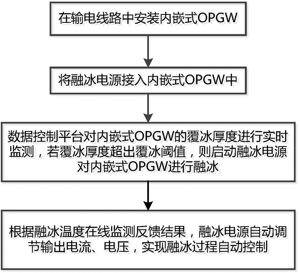
[0039] The invention provides an OPGW deicing method under the condition of non-insulation transformation, which is a method of deicing the optical fiber composite overhead ground wire under the condition of not performing insulation transformation on the transmission line, and realizes the on-line deicing during the deicing process. control. It not only avoids economic and social losses caused by power outages due to ice melting, but also avoids the problem of damage to optical fiber communication functions caused by excessive i...


PUM


Abstract

The invention provides a deicing method for an optical power ground wire (OPGW) under a non-insulated transformation condition. The deicing method comprises the following steps of 1, installing an embedded OPGW in a power transmission line; 2, connecting a deicing power supply to the embedded OPGW; 3, monitoring the ice coating thickness and the deicing temperature of the embedded OPGW in real time by a data control platform, and starting the deicing power supply to deice the embedded OPGW if the ice coating thickness exceeds an ice coating threshold value; and 4, automatically adjusting a current and a voltage output from the deicing power supply according to real-time feedback data of the deicing temperature so as to achieve automatic control on a deicing process. Compared with the prior art, the deicing method for the OPGW under the non-insulated transformation condition, provided by the invention, has the advantages that the deicing of the OPWG in a non-powercut state of a circuit is achieved, meanwhile, the deicing temperature is monitored on line, and unmanned operation can be achieved.

Description

technical field [0001] The invention relates to an OPGW ice-melting method, in particular to an OPGW ice-melting method under non-insulation transformation conditions. Background technique [0002] There are many types of icing on transmission lines, including wet snow, mixed rime, rime, rain rime, freezing fog and freezing rain. Icing is mainly formed by the combination of conditions such as wind speed, air temperature and air humidity, and it will appear repeatedly in specific areas. The main hazards of the power grid in the early stage of icing or when the ice disaster is relatively light are transmission line accidents caused by icing flashover, conductor galloping and ice-off jumping. With the development of the disaster and the intensification of icing, the icing load acting on the tower will exceed the design value (referred to as "over-icing load"), which will lead to disconnection, tower overturning, and in severe cases, it may cause power grid disconnection or eve...

Claims


Application Information

Patent Timeline
IPC IPC(8): H02G7/16
Inventor 张晔雷煜卿陈希
Owner CHINA ELECTRIC POWER RES INST
Why Eureka
Try Eureka