
Packaging structure and its manufacturing method

一种封装结构、制法的技术,应用在半导体/固态器件制造、电气元件、电固体器件等方向,能够解决功能受限等问题

Inactive Publication Date: 2016-11-23
SILICONWARE PRECISION IND CO LTD
View PDF4 Cites 5 Cited by
  • Summary
  • Abstract
  • Description
  • Claims
  • Application Information

AI Technical Summary

Problems solved by technology

[0013] In view of the lack of the above-mentioned prior art, the present invention provides a packaging structure and its manufacturing method to solve the problem of limited functions caused by the existing packaging structure that can only connect other electronic components downwards

Method used


Image

  • Packaging structure and its manufacturing method
  • Packaging structure and its manufacturing method
  • Packaging structure and its manufacturing method

Examples


Embodiment Construction

[0079] The implementation of the present invention will be described below through specific examples, and those skilled in the art can easily understand other advantages and effects of the present invention from the content disclosed in this specification.

[0080] It should be noted that the structures, proportions, sizes, etc. shown in the drawings attached to this specification are only used to match the content disclosed in the specification, for the understanding and reading of those skilled in the art, and are not used to limit the implementation of the present invention. Limiting conditions, so there is no technical substantive meaning, any modification of structure, change of proportional relationship or adjustment of size, without affecting the effect and purpose of the present invention, should still fall within the scope of the present invention. The disclosed technical content must be within the scope covered. At the same time, terms such as "above" and "a" quoted ...


PUM


Abstract

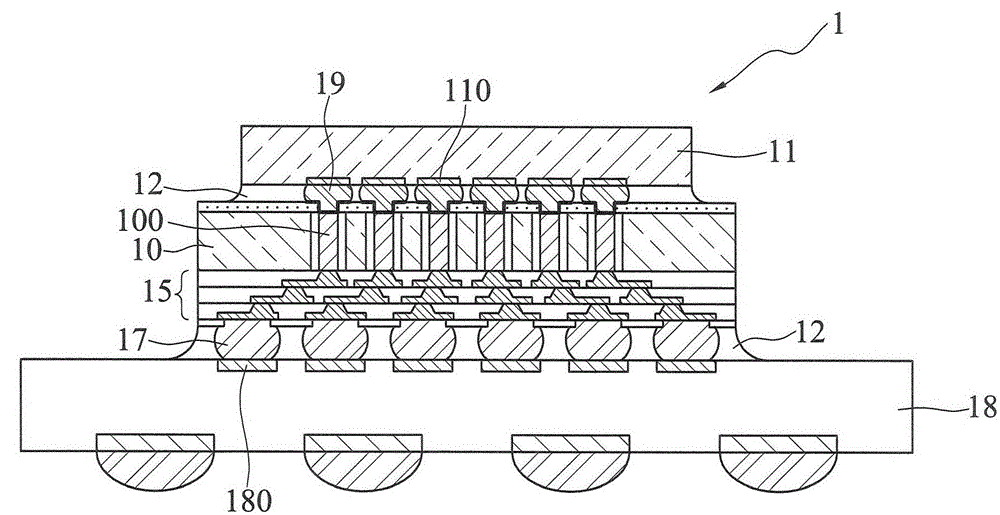
A packaging structure and its manufacturing method are provided; the packaging structure comprises a dielectric layer having a first surface and a second surface opposite to each other; a wiring layer formed in the dielectric layer; an electronic element provided on the first surface of the dielectric layer and electrically connected to the wiring layer; a plurality of conductive posts disposed on a first surface of the dielectric layer and electrically connected with the wiring layer; a package colloid formed on the first surface of the dielectric layer and covering the electronic component and the conductive posts, wherein the package colloid is exposed on the top surface of the conductive post so as to connect with following other electronic units. The conductive posts are electrically connected with the wiring layer, thus solving the limited function problems caused by the existing packing structure can only face downward to connect other electronic elements.

Description

technical field [0001] The invention relates to a packaging structure and its manufacturing method, in particular to a stacked semiconductor packaging structure and its manufacturing method. Background technique [0002] With the vigorous development of the electronic industry, electronic products are gradually moving towards the trend of multi-function and high performance. Technologies currently used in the field of chip packaging, such as Chip Scale Package (CSP), Direct Chip Attached (DCA) or Multi-Chip Module (MCM), etc. type of packaging module. [0003] However, in the flip-chip packaging process, due to the large difference in thermal expansion coefficient between the chip and the circuit substrate, the bumps on the periphery of the chip cannot form a good bond with the corresponding contacts on the circuit substrate, so that the bumps may be peeled off from the circuit substrate. On the other hand, with the increase of the integration degree of the integrated circ...

Claims


Application Information

Patent Timeline
Patent Type & Authority Applications(China)
IPC IPC(8): H01L21/60H01L23/485
CPCH01L2224/83005H01L2224/16227H01L2224/16235H01L2224/32225H01L2224/73204H01L2224/73253H01L2224/81005H01L2924/15311H01L2924/1533H01L2924/18161H01L2924/19103H01L23/3128H01L21/6835H01L25/03H01L2225/1035H01L2225/1058H01L2221/68345H01L25/105H01L2224/92125H01L2224/16225H01L2924/00H01L23/5386H01L23/5385H01L23/5384
Inventor 程吕义吕长伦陈仕卿马光华萧承旭
Owner SILICONWARE PRECISION IND CO LTD
Learn More