Eureka AIR delivers breakthrough ideas for toughest innovation challenges, trusted by R&D personnel around the world.

A pay-off tension control device for cable forming machine

A technology of pay-off tension and control device, used in cable/conductor manufacturing, electrical components, circuits, etc., to solve problems such as exceeding the quality range and excessive tension

Active Publication Date: 2017-09-12
HEFEI SMARTER TECH GROUP CORP
View PDF1 Cites 0 Cited by
  • Summary
  • Abstract
  • Description
  • Claims
  • Application Information

AI Technical Summary

Problems solved by technology

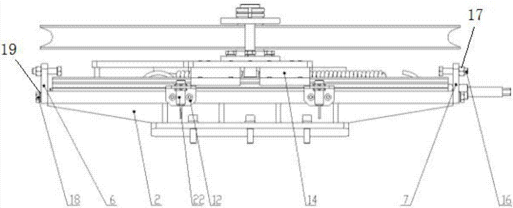
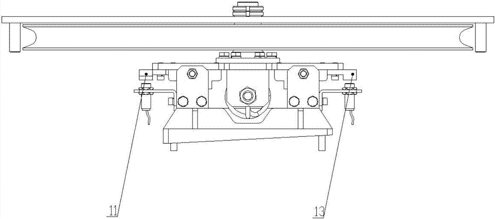
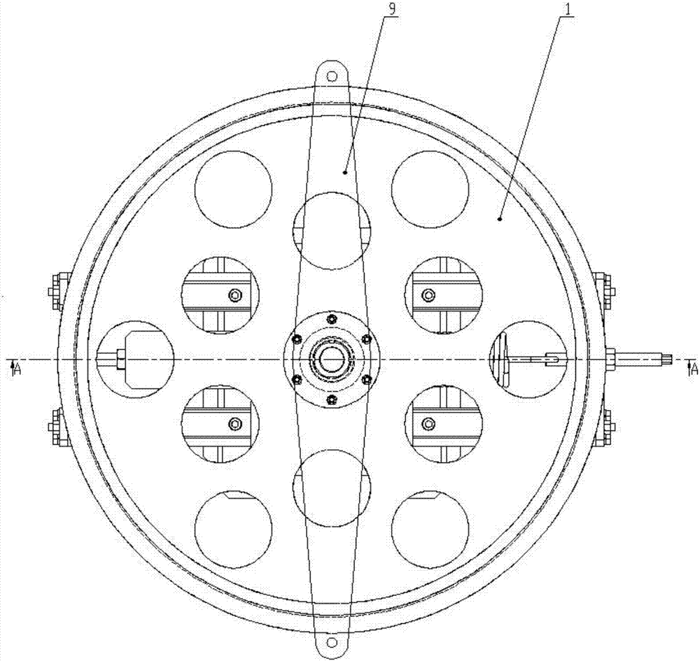
[0007] The purpose of the present invention is to provide a pay-off tension control device for a cable forming machine, which controls the tension of the cable through the deformation of the spring, simulates the proximity switch and pays off synchronously, and uses a double linear guide rail structure for the tension wheel to move. The limit protection structure and the electrical limit protection structure protect the movement of the tension wheel mechanism, which solves the problem of excessive tension or exceeding the quality range when the cable is twisted and formed

Method used


Image

  • A pay-off tension control device for cable forming machine
  • A pay-off tension control device for cable forming machine
  • A pay-off tension control device for cable forming machine

Examples


Embodiment Construction

[0030] The following will clearly and completely describe the technical solutions in the embodiments of the present invention with reference to the accompanying drawings in the embodiments of the present invention. Obviously, the described embodiments are only some, not all, embodiments of the present invention. Based on the embodiments of the present invention, all other embodiments obtained by persons of ordinary skill in the art without creative efforts fall within the protection scope of the present invention.

[0031] In describing the present invention, it is to be understood that the terms "opening", "upper", "lower", "thickness", "top", "middle", "length", "inner", "surrounding" etc. Indicating orientation or positional relationship is only for the convenience of describing the present invention and simplifying the description, and does not indicate or imply that the components or elements referred to must have a specific orientation, be constructed and operated in a sp...


PUM


Abstract

The invention discloses a laying tension control device used for a cable former. The laying tension control device comprises a fixed seat sliding mechanism, a tension pulley mechanism and a position limitation protection device, wherein one surface of a fixed seat is a horizontal plane and a sliding mechanism is fixed on the surface; the other surface of the fixed seat is an inclined plane, and an inclined angle between the inclined plane and the horizontal plane is 0-5 degrees; the position limitation protection device is fixed at the side of the fixed seat; the tension pulley mechanism is fixed on the sliding mechanism. A cable of the cable former is limited through the tension pulley mechanism, and the tension pulley mechanism is fixed on the sliding mechanism, so that the location moving after stress of the tension pulley mechanism is realized, and the tension is controller through a tension spring; the position limitation protection device protects stable twisting of the cable of the cable former, and when the tension is too big to affect production, the protection is carried out through the position limitation protection device.

Description

technical field [0001] The invention belongs to the technical field of cable forming machines, in particular to a pay-off tension control device for cable forming machines. Background technique [0002] In recent years, the cable industry is facing great challenges, especially in the current world economic downturn, the demand for cables in some fields has even decreased by 50%. At the same time, however, raw material prices and energy costs are gradually increasing. This makes the competition in the cable market extremely fierce and intensifies the competition among manufacturers, which is reflected in product series, product quality and cost. [0003] The structural design and finalization of the optical cable are in the cable forming, and the twisting speed of the cable forming equipment is the bottleneck of the optical cable production. The old generation cable forming machine cannot meet the needs of the optical cable production in terms of process control and producti...

Claims


Application Information

Patent Timeline
Patent Type & Authority Patents(China)
IPC IPC(8): H01B13/00
CPCH01B13/00
Inventor 盛卫国蔚伟李佳鹏潘赵勇徐建何晓庆
Owner HEFEI SMARTER TECH GROUP CORP
Why Eureka
Eureka Blog
Learn More