


Quick Research
Generate reliable direction feasibility study reports for your R&D in just a few steps.

Technical Q&A
Discover and master advanced knowledge NOW. Basics, ideas, possibilities, all at once.

Find Solutions
As an expert in R&D theories, this can generate solutions to your technical problems instantly.

Evaluate Feasibility
Analyze your overall solution with one click, know your potential R&D risks in advance.

Monitor Landscape
Get weekly tech updates, stay abreast of the latest tech innovations and key insights.
Optical fiber light-guiding device and backlight module
A light guide device and backlight module technology, which is applied in the direction of optical fiber light guide, optical waveguide light guide, light guide, etc., can solve the problem of uneven light and so on
- Summary
- Abstract
- Description
- Claims
- Application Information
AI Technical Summary
Problems solved by technology
Method used
Image

Examples
Embodiment Construction
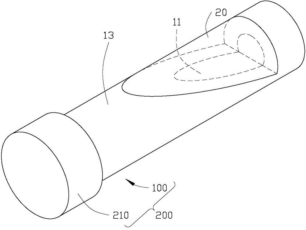
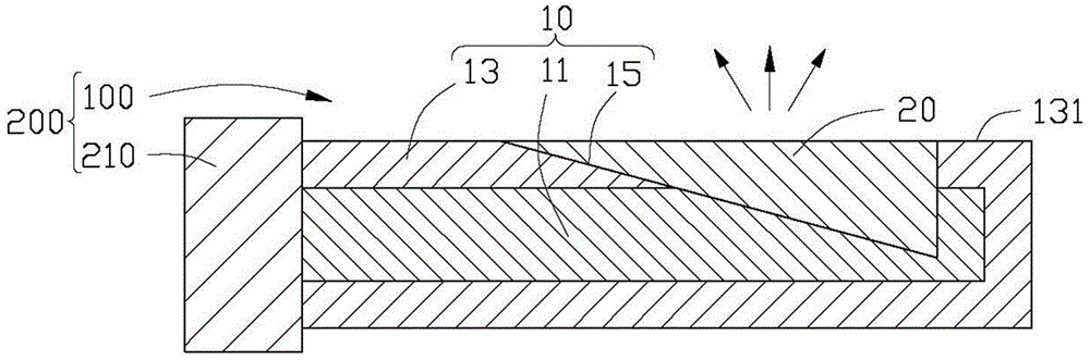
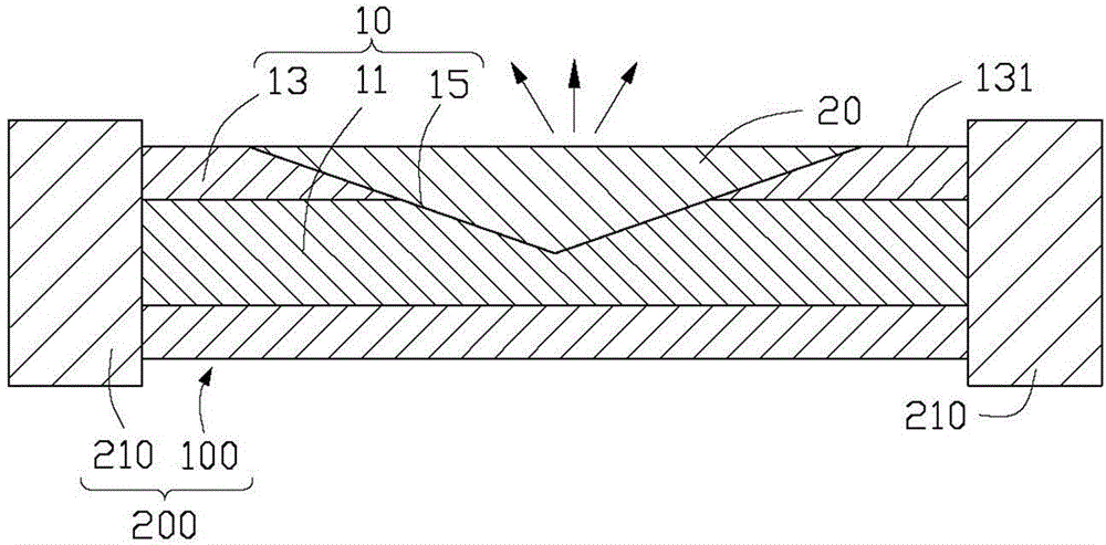
[0020] Please refer to figure 1 and figure 2 , the backlight module 200 of the first embodiment of the present invention includes a fiber optic light guiding device 100 and an incident light source 210 . The optical fiber light guiding device 100 includes an optical fiber 10 . The diameter of the optical fiber 10 is 375 μm-500 μm. The optical fiber 10 includes a core 11 and a cladding 13 covering the core 11 and coaxial with the core 11 . The cladding layer 13 is made of polymer plastic. The diameter of the fiber core 11 is 125 μm-350 μm. The incident light source 210 is disposed near one end of the optical fiber 10 . The optical fiber 10 is provided with an inclined groove 15 towards the axial direction of the fiber core 11 by the outer wall 131 of the cladding 13, the groove 15 is arranged along the extending direction of the optical fiber 10, and the depth of the groove 15 is determined by One end close to the incident light source 210 of the optical fiber 10 gradual...
PUM
 Abstract
Description
Claims
Application Information
 - R&D Engineer
- R&D Manager
- IP Professional
- Industry Leading Data Capabilities
- Powerful AI technology
- Patent DNA Extraction
Browse by: Latest US Patents, China's latest patents, Technical Efficacy Thesaurus, Application Domain, Technology Topic, Popular Technical Reports.
© 2024 PatSnap. All rights reserved.Legal|Privacy policy|Modern Slavery Act Transparency Statement|Sitemap|About US| Contact US: help@patsnap.com