Gear control method, gear control circuit and electric heater
A control circuit and control method technology, applied in the field of circuits, can solve problems such as inability to control the target circuit
- Summary
- Abstract
- Description
- Claims
- Application Information
AI Technical Summary
Problems solved by technology
Method used
Image
Examples
Embodiment 1
[0020] According to an embodiment of the present invention, a gear position control method embodiment is provided. It should be noted that the steps shown in the flow chart of the accompanying drawings can be executed in a computer system such as a set of computer-executable instructions, and, Although a logical order is shown in the flowcharts, in some cases the steps shown or described may be performed in an order different from that shown or described herein.
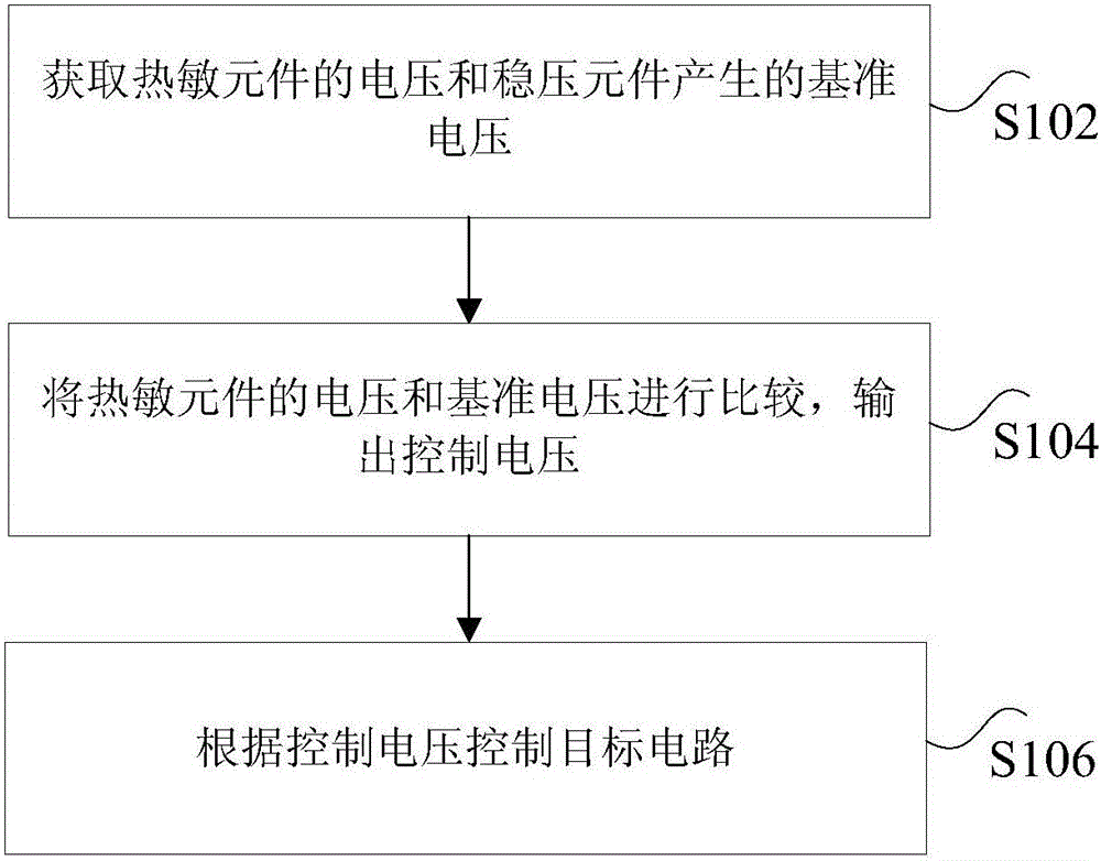
[0021] figure 1 is a flow chart of a gear position control method according to an embodiment of the present invention, such as figure 1 As shown, the method includes the following steps:
[0022] Step S102, obtain the voltage of the thermal element and the reference voltage generated by the voltage stabilizing element, wherein one end of the thermal element is connected to the power supply through the gear resistance and the gear switch, and the voltage of the thermal element changes according to the change of the a...
Embodiment 2
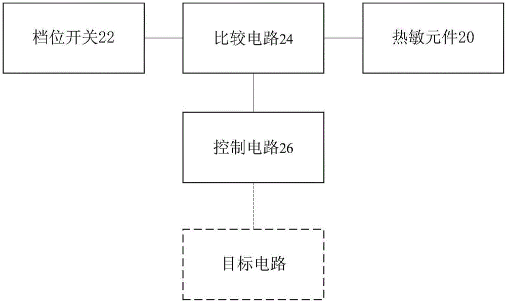
[0045] The present application also provides a gear position control circuit, figure 2 is a structural schematic diagram of a gear position control circuit according to an embodiment of the present invention, such as figure 2 As shown, the gear control circuit includes:
[0046] The thermosensitive element 20 is used to change the resistance value according to the change of the ambient temperature.
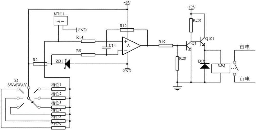
[0047] Specifically, the above thermal element may be an NTC thermistor, and the resistance of the NTC decreases as the ambient temperature increases. In the case of a thermal element with a positive coefficient, the resistance value of the thermal element increases with the increase of the ambient temperature; in the case of a negative coefficient thermal element, the resistance value of the thermal element increases with Decreases with an increase in ambient temperature.
[0048] Gear switch 22, one end is connected to the power supply, the other end is connected to the com...
Embodiment 3
[0092] The present application also provides an electric heater, including any gear position control circuit in Embodiment 2.
[0093] In an optional embodiment, taking the NTC as an example of the thermal element, the resistance of the NTC decreases as the ambient temperature increases. When the electric heater is fixed at a gear, the lower the ambient temperature, The smaller the resistance of the NTC is, the smaller the voltage will be when the corresponding NTC divides the voltage with the gear resistance. When the voltage divided by the NTC is lower than the reference voltage, the comparator output of the gear control circuit will be zero, making the relay closed. .
[0094] For example, the above-mentioned electric heater can include three gears, which are respectively high-grade, medium-range, and low-grade. The selected gear is the high gear. If the temperature threshold set by the high gear is 28°C, after the user turns on the electric heater, the ambient temperature...
PUM
 Abstract
Description
Claims
Application Information
 - R&D Engineer
- R&D Manager
- IP Professional
- Industry Leading Data Capabilities
- Powerful AI technology
- Patent DNA Extraction
Browse by: Latest US Patents, China's latest patents, Technical Efficacy Thesaurus, Application Domain, Technology Topic, Popular Technical Reports.
© 2024 PatSnap. All rights reserved.Legal|Privacy policy|Modern Slavery Act Transparency Statement|Sitemap|About US| Contact US: help@patsnap.com


