
Rotary compressor

A technology of rotary compressor and compression chamber, applied in the field of compressors, can solve problems such as compressor performance decline, and achieve the effect of reducing impact and vibration

Active Publication Date: 2020-08-14
HEFEI LINGDA COMPRESSOR +1
View PDF4 Cites 0 Cited by
  • Summary
  • Abstract
  • Description
  • Claims
  • Application Information

AI Technical Summary

Problems solved by technology

[0005] The embodiment of the present invention provides a rotary compressor, which can effectively buffer the refrigerant pressure pulsation of the compressor pump body in the compression and exhaust stages, reduce the vibration and noise of the compressor, and solve the problem of compressor performance degradation caused by the traditional resonance cavity scheme

Method used


Image

  • Rotary compressor
  • Rotary compressor
  • Rotary compressor

Examples


Embodiment Construction

[0031] The present invention will be described in further detail below in conjunction with the accompanying drawings and specific embodiments, but not as a limitation of the present invention.

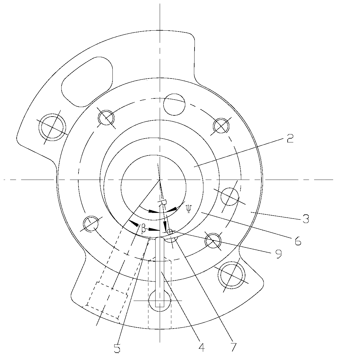
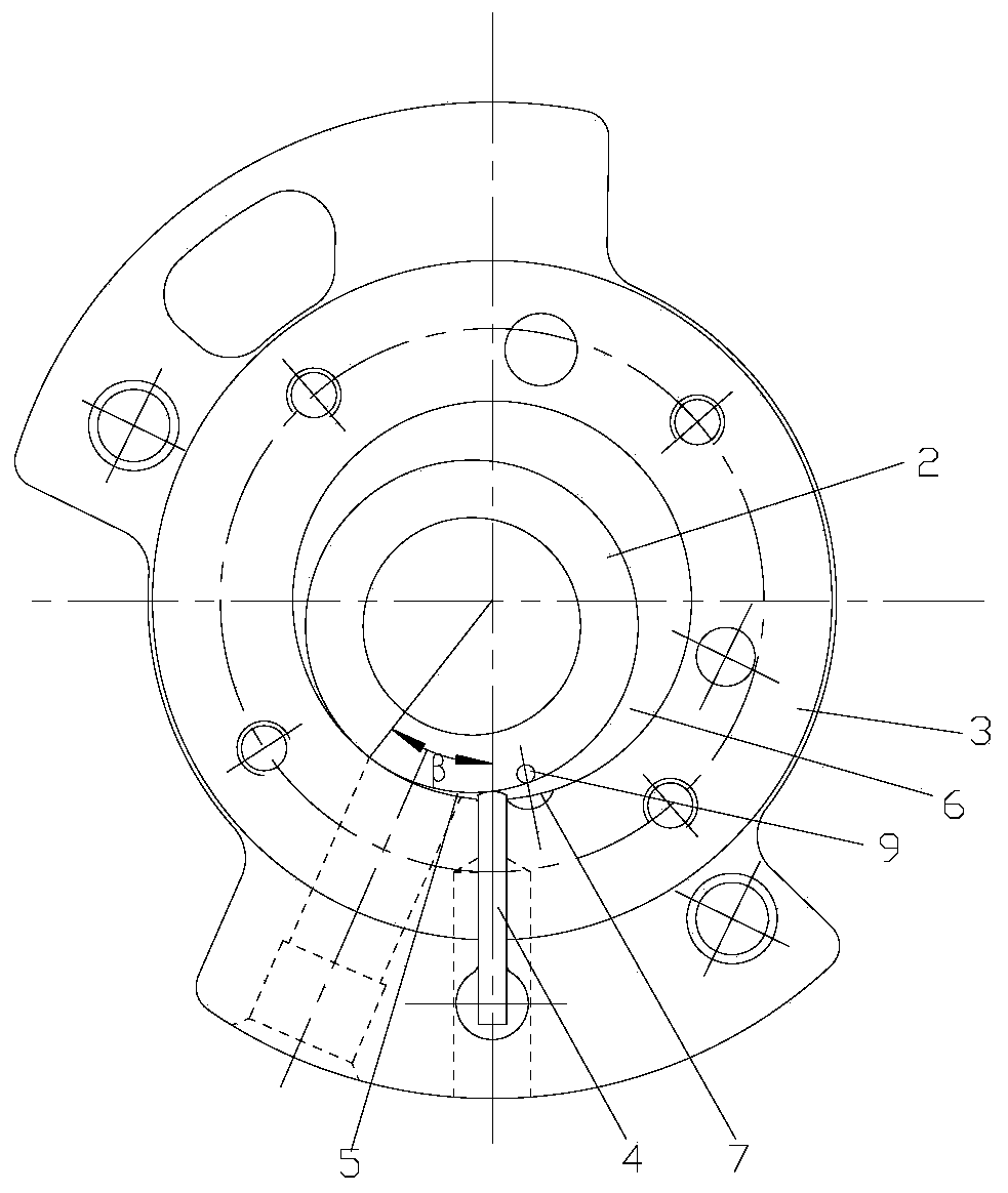
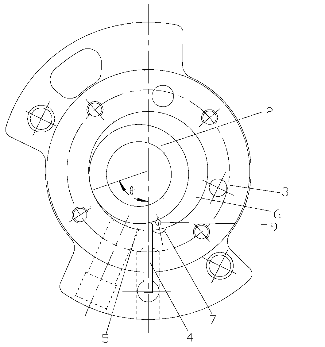
[0032] see in conjunction Figure 1 to Figure 13 As shown, according to the embodiment of the present invention, the rotary compressor includes a cylinder head plate 1, a rolling piston 2 and a pump body cylinder 3, the pump body cylinder 3 has a piston cavity, the rolling piston 2 is rollingly arranged in the piston cavity, and the pump body cylinder 3 is slidably provided with a slide plate 4, one end of the slide plate 4 abuts against the outer wall of the rolling piston 2, and divides the piston chamber into a suction chamber 5 and a compression chamber 6, and a resonant chamber 8 is provided on the cylinder head plate 1, and the pump body cylinder 3 is provided with an exhaust port 7, and the resonance chamber 8 and the compression chamber 6 are not connected when the rotary compr...


PUM


Abstract

The invention discloses a rotary compressor. The rotary compressor comprises a cylinder cover plate, a rolling piston and a pump body cylinder; a piston cavity is formed in the pump body cylinder; the rolling piston is arranged in the piston cavity in a rolling manner; a slide plate is slidingly arranged on the pump body cylinder; one end of the slide plate is butted against the outer wall of the rolling piston; the piston cavity is divided into an air sucking cavity and a compression cavity; a resonance cavity is arranged on the cylinder cover plate; an exhaust port is formed in the pump body cylinder; and the resonance cavity and the compression cavity are not communicated when the rotary compressor is located in an air sucking phase, and are communicated when the rotary compressor is located in compression and exhaust phases. The rotary compressor can effectively buffer the refrigerant pressure pulsation of a compressor pump body in the compression and exhaust phase, reduces the compressor vibration and noise, and solves the performance weakening problem caused by a traditional resonance cavity scheme.

Description

technical field [0001] The present invention relates to the technical field of compressors, in particular to a rotary compressor. Background technique [0002] In the existing rotary compressor, the pump body is usually composed of crankshaft, upper flange, upper muffler, roller, cylinder, lower flange, lower muffler and other components. In the compressor with the pump body of the lower exhaust structure, the high-pressure gas is discharged from the lower exhaust port into the cavity of the lower muffler, and then discharged to the upper muffler through the single-pipe channel between the lower flange-cylinder-upper flange outside of the device or pump body. [0003] During the working process of the roller compressor pump body, the refrigerant will generate large pressure pulsations during the compression and exhaust stages, which will cause the overall vibration of the compressor, making the vibration of the whole machine more severe, and the pressure pulsation will also...

Claims


Application Information

Patent Timeline
Patent Type & Authority Patents(China)
IPC IPC(8): F04C18/356F04C29/00
CPCF04C18/3562F04C29/00F04C29/061
Inventor 文智明张荣婷张要思谷欢欢张金圈
Owner HEFEI LINGDA COMPRESSOR
Learn More