
carcass transfer ring

A transfer ring and carcass technology, applied in the field of rubber machinery, can solve problems such as low efficiency and inconvenient operation, and achieve the effects of ensuring carcass quality, improving clamping stability, and low cost

Active Publication Date: 2018-10-02
QINGDAO MESNAC ELECTROMECHANICAL ENG
View PDF5 Cites 0 Cited by
  • Summary
  • Abstract
  • Description
  • Claims
  • Application Information

AI Technical Summary

Problems solved by technology

[0005] In order to solve the existing problems of inconvenient operation and low efficiency when adjusting the carcass transfer ring according to different carcass specifications, the present invention proposes a new carcass transfer ring, and its technical scheme is as follows:

Method used


Image

  • carcass transfer ring
  • carcass transfer ring
  • carcass transfer ring

Examples


Embodiment Construction

[0025] The present invention will be described in further detail below in conjunction with the accompanying drawings and specific embodiments.

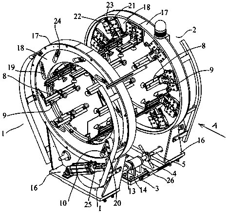
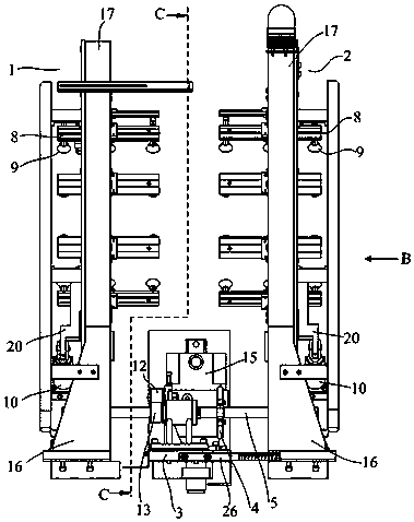
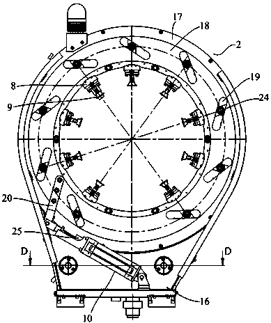
[0026] refer to Figure 2 to Figure 5 , The carcass transmission ring of the present embodiment, the left transmission ring body 1, the right transmission ring body 2, the screw seat 3, the adjustment handle 4, the transmission screw 5 and the left screw nut 6 and the right screw nut 7. The left transmission ring body 1 and the right transmission ring body 2 are arranged oppositely, and the central axes coincide, and the axial direction of the transmission screw 5 is parallel to the central axes of the two transmission ring bodies 1 and 2; the left screw nut 6 is fixed on the left transmission ring body 1. The upper and right screw nuts 7 are fixed on the right transmission ring 2, and the transmission screw 5 is installed on the screw seat 3, and its two ends are respectively connected with the left screw nut 6 and the right screw nu...


PUM


Abstract

The invention provides a tire body transfer ring. Operation is convenient and efficiency is high when adjustment is conducted according to the specifications of tire bodies. The tire body transfer ring comprises a left transfer ring body, a right transfer ring body, a screw rod seat, an adjusting handle, transmission screw rods, left nuts and right nuts. The left nuts and the right nuts are fixedly arranged on the left transfer ring body and the right transfer ring body correspondingly. The transmission screw rods are mounted on the screw rod seat, and the two ends of each transmission screw rod are connected with the corresponding left nut and the corresponding right nut in a screwed fit mode. The adjusting handle is fixedly arranged on one transmission screw rod. Suction cup seats are evenly distributed on the left transfer ring body, and suction cup seats are evenly distributed on the right transfer ring body. Vacuum suction cups are arranged on the suction cup seats correspondingly. And cylinders are further mounted on the left transfer ring body and the right transfer ring body. The two ring bodies are arranged, the distance between the two ring bodies can be conveniently adjusted through the adjusting handle, the requirements for transfer of tire bodies of multiple specifications are met, and production efficiency is greatly improved; and it is ensured that the edges of the tire bodies of multiple specifications can be sucked, the phenomenon of drooping of the tire bodies is avoided, and tire body quality is guaranteed.

Description

technical field [0001] The invention belongs to the field of rubber machinery, and in particular relates to a carcass transfer ring for manufacturing semi-steel tire blanks. Background technique [0002] In the tire blank manufacturing device and process method, the carcass transfer ring is an important part of the tire building machine. Its main function is to transfer the ready-fit carcass on the carcass fitting drum to the building drum by grabbing. Forming process. In practical applications, the synchronization and coaxiality of the suction cups on the carcass transfer ring will have a greater impact on the transfer accuracy and molding accuracy of the carcass. Especially for semi-steel tires, the carcass does not contain steel wires, so it cannot be grasped by magnetic suction cups, and usually grasped by vacuum adsorption. [0003] The existing carcass transfer ring mainly includes a cylinder, a transfer ring body and a suction cup seat, etc., the number of the sucti...

Claims


Application Information

Patent Timeline
Patent Type & Authority Patents(China)
IPC IPC(8): B29D30/26
Inventor 杨慧丽戚坤钟明亮
Owner QINGDAO MESNAC ELECTROMECHANICAL ENG
Learn More