Servo boost slicing device
A technology of a slicing device and a power device, which is applied in the fields of slicing devices and servo-propelled slicing devices, can solve the problems of inability to meet the change of cutting size, unfavorable for production efficiency, and unfavorable for large-scale production.
- Summary
- Abstract
- Description
- Claims
- Application Information
AI Technical Summary
Problems solved by technology
Method used
Image
Examples
Embodiment 1
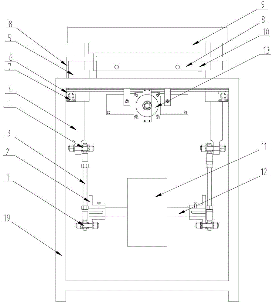
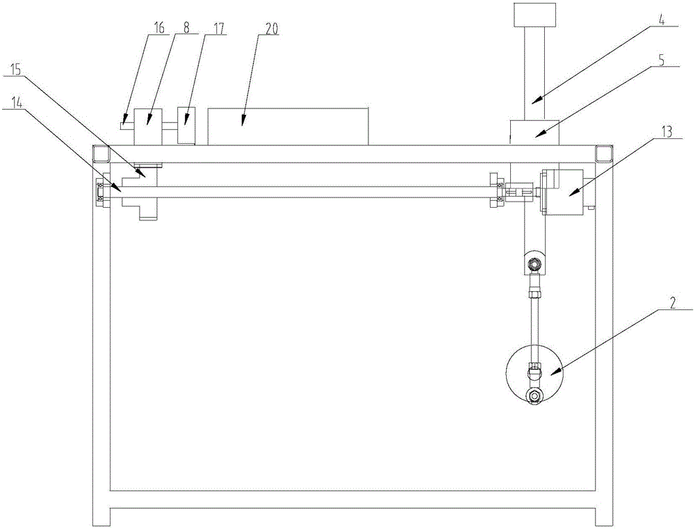
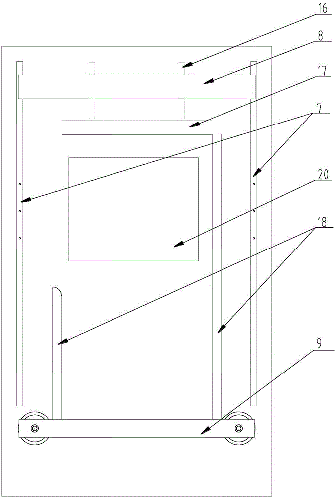
[0022] As shown in the drawings, a servo propulsion slicing device includes: stud 1, turntable 2, transmission rod 3, guide post 4, guide sleeve 5, slider 6, slide rail 7, push rod mounting plate 8, cutter installation Plate 9, cutter 10, cutter power unit 11, transmission shaft 12, push plate power unit 13, leading screw 14, nut 15, push rod 16, push plate 17, baffle plate 18, frame 19, wherein, cutter 10 is fixed on the cutter mounting plate 9 by bolts, and there is a threaded hole at the center of the top of the guide post 4. On the frame 19, bearings are installed inside the guide sleeve 5, and the guide post 4 is slidingly connected; the guide post 4 is connected with the transmission rod 3 through the stud 1, and the transmission rod 3 is connected with the turntable 2 through the stud 1; the center of the turntable 2 is connected with the drive The shaft 12 is fixed by means of screw compression, the cutter power unit 11 is equipped with a speed reducer, and the transmi...
Embodiment 2
[0026] As shown in the drawings, a servo propulsion slicing device includes: stud 1, turntable 2, transmission rod 3, guide post 4, guide sleeve 5, slider 6, slide rail 7, push rod mounting plate 8, cutter installation Plate 9, cutter 10, cutter power unit 11, transmission shaft 12, push plate power unit 13, leading screw 14, nut 15, push rod 16, push plate 17, baffle plate 18, frame 19, wherein, cutter 10 is fixed on the cutter mounting plate 9, the two sides of the cutter mounting plate 9 are fixedly connected with the guide post 4, the guide sleeve 5 is fixed on the frame 19, and is slidably connected with the guide post 4; The rod 3 is connected, the transmission rod 3 is connected with the turntable 2 through the stud 1; the center of the turntable 2 and the transmission shaft 12 are fixed by screw compression, the cutter power device 11 is equipped with a reducer, and the drive shaft 12 passes through the internal gear of the reducer connect. The push rod 16 is installe...
Embodiment 3
[0030]As shown in the drawings, a servo propulsion slicing device includes: stud 1, turntable 2, transmission rod 3, guide post 4, guide sleeve 5, slider 6, slide rail 7, push rod mounting plate 8, cutter installation Plate 9, cutter 10, cutter power unit 11, transmission shaft 12, push plate power unit 13, leading screw 14, nut 15, push rod 16, push plate 17, baffle plate 18, frame 19, wherein, cutter 10 is fixed on the cutter mounting plate 9, the two sides of the cutter mounting plate 9 are fixedly connected with the guide post 4, the guide sleeve 5 is fixed on the frame 19, and is slidably connected with the guide post 4; The rod 3 is connected, the transmission rod 3 is connected with the turntable 2 through the stud 1; the center of the turntable 2 is fixed with the transmission shaft 12, the cutter power device 11 is equipped with a reducer, and the drive shaft 12 is connected through the internal gear of the reducer. The push rod 16 is installed on the push rod mountin...
PUM
 Abstract
Description
Claims
Application Information
 - R&D Engineer
- R&D Manager
- IP Professional
- Industry Leading Data Capabilities
- Powerful AI technology
- Patent DNA Extraction
Browse by: Latest US Patents, China's latest patents, Technical Efficacy Thesaurus, Application Domain, Technology Topic, Popular Technical Reports.
© 2024 PatSnap. All rights reserved.Legal|Privacy policy|Modern Slavery Act Transparency Statement|Sitemap|About US| Contact US: help@patsnap.com


