
Pin puller

A pin puller and pin rod technology, applied in the field of overhead transmission lines, can solve the problems of difficulty in ensuring the direction of force application, inconvenient operation, unqualified quality, etc., and achieve the effect of easy force application, convenient operation, and ensuring normal use.

Inactive Publication Date: 2017-10-03
JIANGXI ELECTRIC VOCATIONAL & TECHN COLLEGE +1
View PDF6 Cites 0 Cited by
  • Summary
  • Abstract
  • Description
  • Claims
  • Application Information

AI Technical Summary

Problems solved by technology

With the development of the power transmission industry, the amount of insulators is increasing, and the amount of locking pins is also increasing. The weight of the locking pins is only about 1 / 250 of the insulator, but if the insulator string is not equipped with locking pins or the quality of the locking pins Unqualified or even improper installation, the possible losses are immeasurable, and there is a great potential safety hazard
[0004] When replacing the insulating porcelain bottle on the overhead transmission line, it is necessary to use wire pliers to manually pull out the pin, that is, the staff uses wire pliers to clamp the locking pin, and then pulls out the locking pin forcefully, because the pin is pulled out at high altitude. Operation, inconvenient operation, low safety, and because it is difficult to ensure that the force direction when pulling out the pin is consistent with the pulling out direction of the locking pin, resulting in insufficient force, the locking pin is not easy to pull out

Method used


Image

  • Pin puller
  • Pin puller
  • Pin puller

Examples


Embodiment Construction

[0045] When replacing the insulating porcelain bottle on the overhead transmission line, it is necessary to use wire pliers to manually pull out the pin, that is, the staff uses wire pliers to clamp the locking pin, and then pulls out the locking pin forcefully, because the pin is pulled out at high altitude. Operation, inconvenient operation, low safety, and because it is difficult to ensure that the direction of force applied when pulling out the pin is consistent with the pulling out direction of the locking pin, resulting in insufficient strength, the locking pin is not easy to be pulled out.

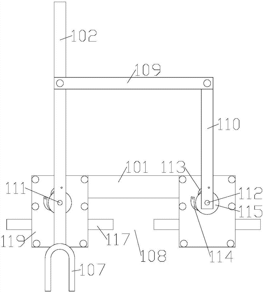
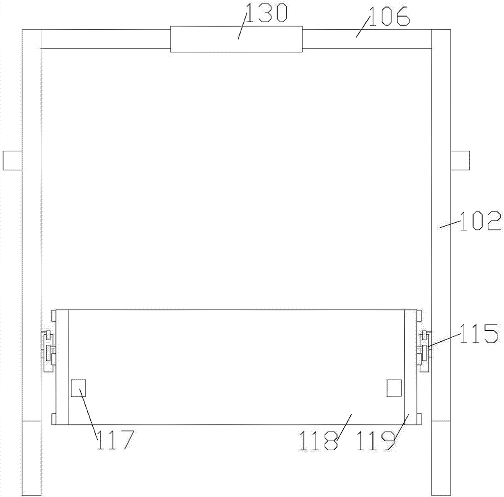
[0046] In order to improve the above problems, the present invention provides a pin puller, including a fixing piece, a pin pulling piece and a positioning piece, the pin pulling piece includes at least one pin pulling lever arranged side by side, the pin pulling lever is rotatably arranged on the fixing piece, The length direction of the positioning piece is perpendicular to the len...


PUM


Abstract

The invention provides a pin puller and belongs to the overhead transmission line field. The pin puller comprises a fixing part, a pin pulling part and a locating part; the pin pulling part comprises at least two pin pulling rods arranged side by side, the pin pulling rods are square rods, and the outer sides of the pin pulling rods are sleeved with insulation layers, and the pin pulling rods are rotatably arranged on the fixing part; and the length direction of the locating part is perpendicular to the length direction of the pin pulling rods. The locating part abuts against a socket and one end of each pin pulling rod is inserted into a locking pin, so that the pin puller is formed into a lever; and a certain force is applied to the end, away from the locking pin, of each pin pulling rod, and force is applied to the locking pins through the pin pulling rods and the locking pins are pulled out. According to the pin puller, firstly, the locking pins can be pulled out more easily by adopting the leverage principle; secondly, force application becomes easier as force can be applied to the end of each pin pulling rod from different angles, and operation is more convenient; and finally, one hand can operate the pin puller for pin pulling, the pin pulling progress is safer and more reliable, and electricity does not need to be cut off in the pin pulling progress.

Description

technical field [0001] The invention relates to the field of overhead power transmission lines, in particular to a pin puller. Background technique [0002] Insulator, commonly known as insulating porcelain bottle, is a device installed between conductors of different potentials or between conductors and ground potential components. It can withstand voltage and mechanical stress. It is a special insulation control that can be used in overhead transmission lines. play an important role. [0003] Locking pins, commonly known as spring pins, are available in two types, R-shaped and W-shaped, and are important components of suspension insulator strings. With the development of the power transmission industry, the amount of insulators is increasing, and the amount of locking pins is also increasing. The weight of the locking pins is only about 1 / 250 of the insulator, but if the insulator string is not equipped with locking pins or the quality of the locking pins If it is unqual...

Claims


Application Information

Patent Timeline
Patent Type & Authority Patents(China)
IPC IPC(8): B25B27/02
CPCB25B27/02
Inventor 杜中庆陈跃中朱小军
Owner JIANGXI ELECTRIC VOCATIONAL & TECHN COLLEGE
Learn More