Position feedback device for working roller of multi-roller mill and position feedback control method of position feedback device

A positioning feedback and control method technology, applied in the rolling field of continuous rolling mills, can solve problems such as equipment failure, product quality, unbalanced load, broken strip shape, hidden dangers, etc., to meet the needs of normal work and ensure stability and continuity. Effect

Inactive Publication Date: 2016-11-23
BAOSTEEL STAINLESS STEEL
View PDF6 Cites 6 Cited by
  • Summary
  • Abstract
  • Description
  • Claims
  • Application Information

AI Technical Summary

Problems solved by technology

[0005] The usual side support device is directly controlled by the oil cylinder, which has hydraulic instability caused by frequent changes in large loads, and the life of the oil cylinder is short, which can easily lead to equipment failures such as unbalanced load breakage or poor plate shape and hidden product quality, which seriously affects the stable and continuous production of the unit. and product pass rate

Method used


Image

  • Position feedback device for working roller of multi-roller mill and position feedback control method of position feedback device
  • Position feedback device for working roller of multi-roller mill and position feedback control method of position feedback device
  • Position feedback device for working roller of multi-roller mill and position feedback control method of position feedback device

Examples


Embodiment Construction

[0081] Next, a positioning feedback device for work rolls of a multi-roll rolling mill and a positioning feedback control method thereof according to the present invention will be further described in detail according to the accompanying drawings and specific embodiments.

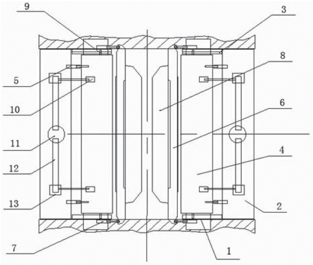
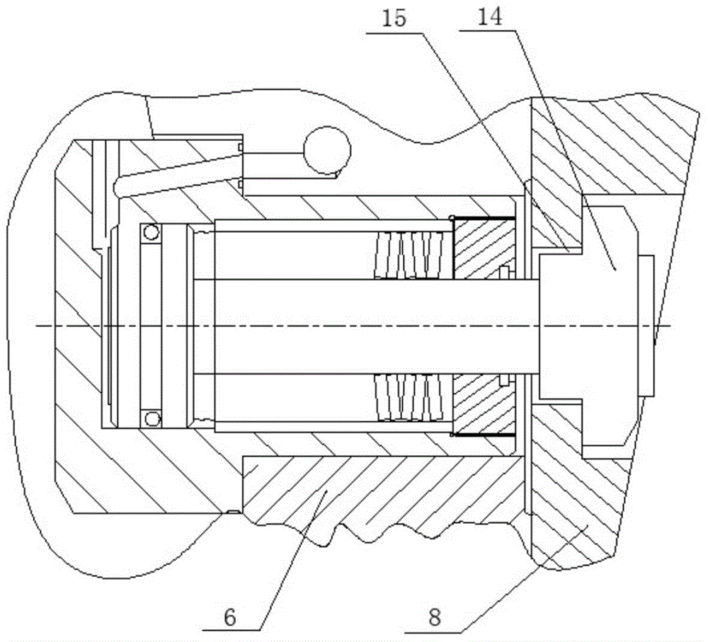
[0082] Such as figure 1 , 2 A positioning feedback device for the work rolls of a multi-roll rolling mill is shown, which is used to adjust the positioning of the roll system after the roll change and before the roll test, so as to realize effective support for the roll system, including: located on the center line of the stand in the up and down, front and rear Four identical mechanisms arranged in mirror symmetry, each of which includes:

[0083] a transition plate (1) arranged on the frame,

[0084] a fixed arm (2) detachably fixed on the transition plate,

[0085] The linear guide rail (3) set on the transition plate,

[0086] Traversing arm (4) arranged in the linear guide rail,

[0087] Traverse ...


PUM


Abstract

The invention discloses a position feedback device for a working roller of a multi-roller mill and a position feedback control method of the position feedback device. A control system is matched with the corresponding position feedback device to perform position adjustment control on a roller system after a roller is replaced and before a roller leaning test is performed, so that effective support for the roller system is realized; transverse movement oil cylinders drive transverse movement arms to move along linear guide rails to reach initial set positions; rotating oil cylinders drive rotating arms to reach mechanical zero positions; position sensors are matched with the control system and the transverse movement oil cylinders to enable the transverse movement arms to reach positions where the transverse movement arms are in no-clearance surface contact with the rotating arms; and load sensors are matched with the control system and adjustment devices which are arranged at the central line positions of fixed arms and are used for adjusting the transverse movement arms so as to drive the transverse movement arms, the rotating arms and side supporting roller boxes to achieve the effect that a set value of a load difference between two sides can be met. The position feedback device for the working roller of the multi-roller mill and the position feedback control method of the position feedback device are high in load-deflection resistance, the stability of the roller system is high, and the surface quality of a rolled strip is high; and the stability of the rolling working condition and the rolling continuity are guaranteed.

Description

technical field [0001] The invention belongs to the rolling field of continuous rolling mills, and in particular relates to a positioning feedback device and a positioning feedback control method for working rolls of a multi-roll rolling mill. Background technique [0002] The carbon steel strip continuous rolling mill usually adopts six-roll configuration, including backup rolls, intermediate rolls and work rolls. Due to the physical characteristics of carbon steel, the roll diameter of the work rolls is usually relatively large, generally above 250mm, which can not only meet the reduction rate requirements , and the roll diameter and length ratio of the work roll can fully meet the requirements. [0003] Stainless steel is characterized by high deformation resistance, which is generally twice as high as that of ordinary carbon steel; due to the formation of deformed martensite during cold working, the work hardening rate is fast, and greater rolling capacity and load are r...

Claims


Application Information

Patent Timeline
IPC IPC(8): B21B28/02B21B37/00
Inventor 叶冬柏
Owner BAOSTEEL STAINLESS STEEL
Why Eureka
Try Eureka