Device and motion state detection method

A technology of motion state and detection method, which is applied in the direction of measuring devices, surveying and navigation, instruments, etc., can solve the problems of increased error, high timeliness and difficulty in accurately controlling the driving conditions of equipment, and achieve the effect of correcting the deviation of motion trajectory

Active Publication Date: 2020-02-21
LENOVO (BEIJING) LTD
View PDF6 Cites 0 Cited by
  • Summary
  • Abstract
  • Description
  • Claims
  • Application Information

AI Technical Summary

Problems solved by technology

[0003] However, due to factors such as mechanical errors, frictional forces, and changes in ground conditions, there will inevitably be errors between the rotation amount / steering angle of the motion command and the actual rotation amount / steering angle of the wheel. The error between the trajectories will further increase with the driving distance, and it becomes difficult to control the driving situation of the equipment in a timely and precise manner

Method used


Image

  • Device and motion state detection method
  • Device and motion state detection method
  • Device and motion state detection method

Examples


Embodiment Construction

[0027] Hereinafter, specific embodiments of the present invention will be described with reference to the drawings. The following description with reference to the accompanying drawings is provided to assist understanding of example embodiments of the invention as defined by the claims and their equivalents. It includes various specific details to aid in understanding but they are to be regarded as exemplary only. Also, detailed descriptions of functions and constructions well-known in the art will be omitted to make the description clearer and more concise. In the drawings, the same reference numerals generally represent the same components or steps.

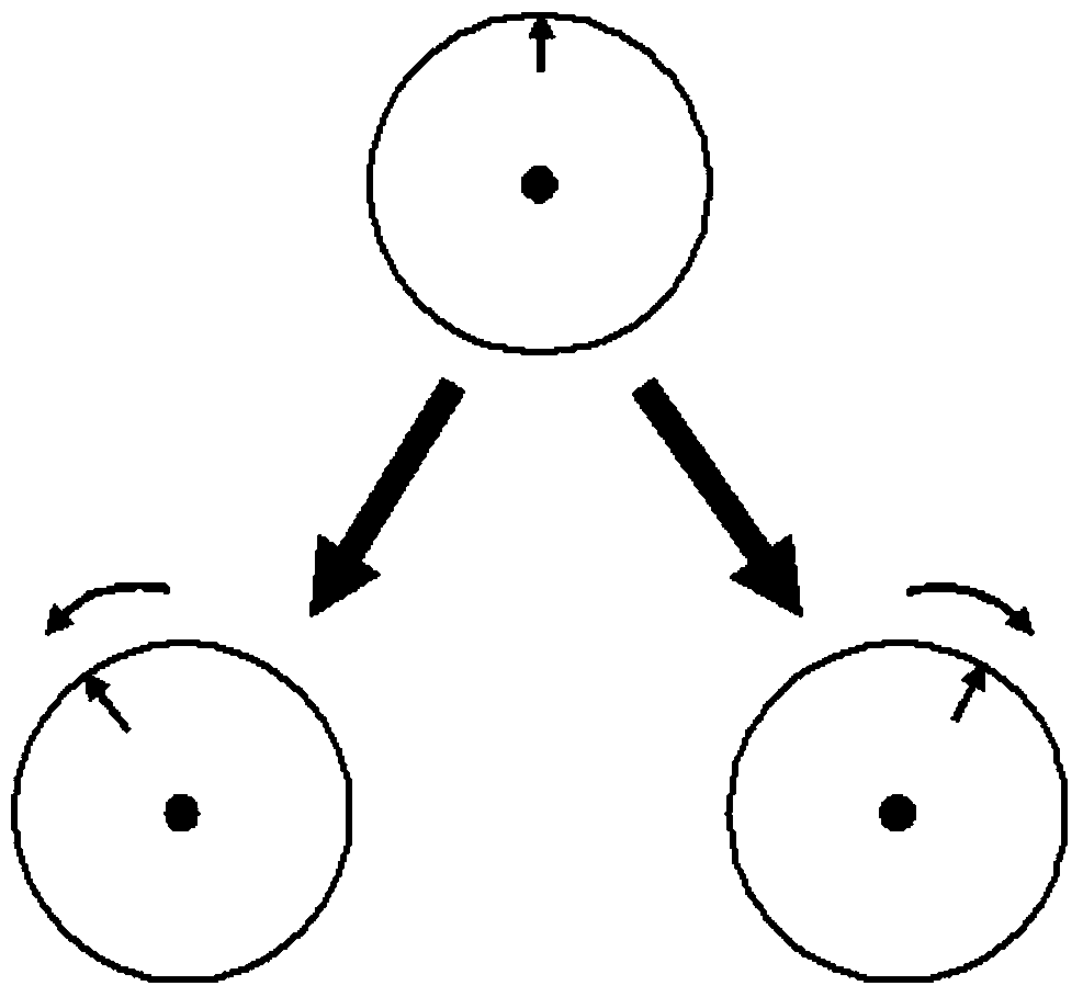
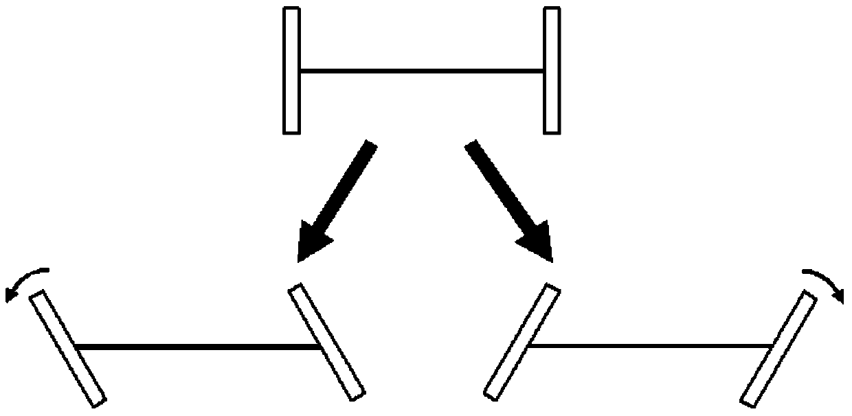
[0028] Here, the equipment involved in the present invention may be equipment such as automobiles with automatic driving functions, intelligent robots, and intelligent flatbed vehicles. The device controls the motion state of the wheel according to the motion command sent by the processor or the remote server, so that it can ...


PUM


Abstract

The invention provides a device with a wheel and a motion state detection device. The wheel can rotate in a first direction around the central axis of the wheel, and the motion state detection device is used to detect the actual motion state of the wheel, wherein the motion state detection device It includes: a light emitter that emits light to the first side of the wheel, wherein a coding pattern is set on the first side, and the coding pattern is aligned with the wheel when the wheel rotates. Rotate together; the photodetector, photograph the first area on the wheel that is irradiated by the emitted light, and obtain the image data of the first area; and the processor, according to the coding pattern and the The image data is used to obtain data related to the actual rotation of the wheel in the first direction.

Description

technical field [0001] The invention relates to a device with a wheel, in particular to a device capable of detecting the motion state of the wheel. Background technique [0002] In recent years, with the development of technologies such as GPS navigation and automatic driving, the technology of using motion commands to control the driving of vehicles with wheels, intelligent robots, and intelligent flatbed vehicles has made great progress. The rotation amount / steering angle of the wheel of the equipment is controlled by motion commands, so as to realize the control of the equipment driving conditions (speed, route, position, etc.). [0003] However, due to factors such as mechanical errors, frictional forces, and changes in ground conditions, there will inevitably be errors between the rotation amount / steering angle of the motion command and the actual rotation amount / steering angle of the wheel. The error between trajectories will further increase with the driving distanc...

Claims


Application Information

Patent Timeline
Patent Type & Authority Patents(China)
IPC IPC(8): H04N5/14H04N5/222H04N5/225G01C23/00
CPCH04N5/144H04N5/2228G01C23/00H04N23/555H04N23/54
Inventor 石彬
Owner LENOVO (BEIJING) LTD
Why Eureka
Try Eureka