Automatic butt joint charging system and automatic butt joint charging method for robot

An automatic docking and charging system technology, applied in battery circuit devices, data exchange chargers, control/regulation systems, etc., can solve problems such as trouble, inconvenience, and inability to charge robots, reduce manual operations, realize automatic docking, Achieve the effect of automatic charging

Active Publication Date: 2016-11-16
BEIJING C&W ELECTRONICS GRP
View PDF6 Cites 23 Cited by
  • Summary
  • Abstract
  • Description
  • Claims
  • Application Information

AI Technical Summary

Problems solved by technology

[0002] The existing charging piles use manual aerial charging for charging the robot. Manual charging is more troublesome. It is very inconvenient for people to plug in the charger in time when the robot is at low voltage inside the robot. Cannot charge the robot when not nearby

Method used


Image

  • Automatic butt joint charging system and automatic butt joint charging method for robot
  • Automatic butt joint charging system and automatic butt joint charging method for robot
  • Automatic butt joint charging system and automatic butt joint charging method for robot

Examples


Embodiment 1

[0037] Embodiment 1. A robot automatic docking and charging system.

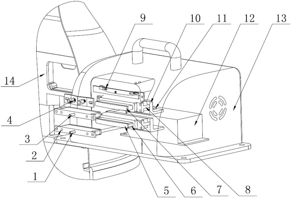
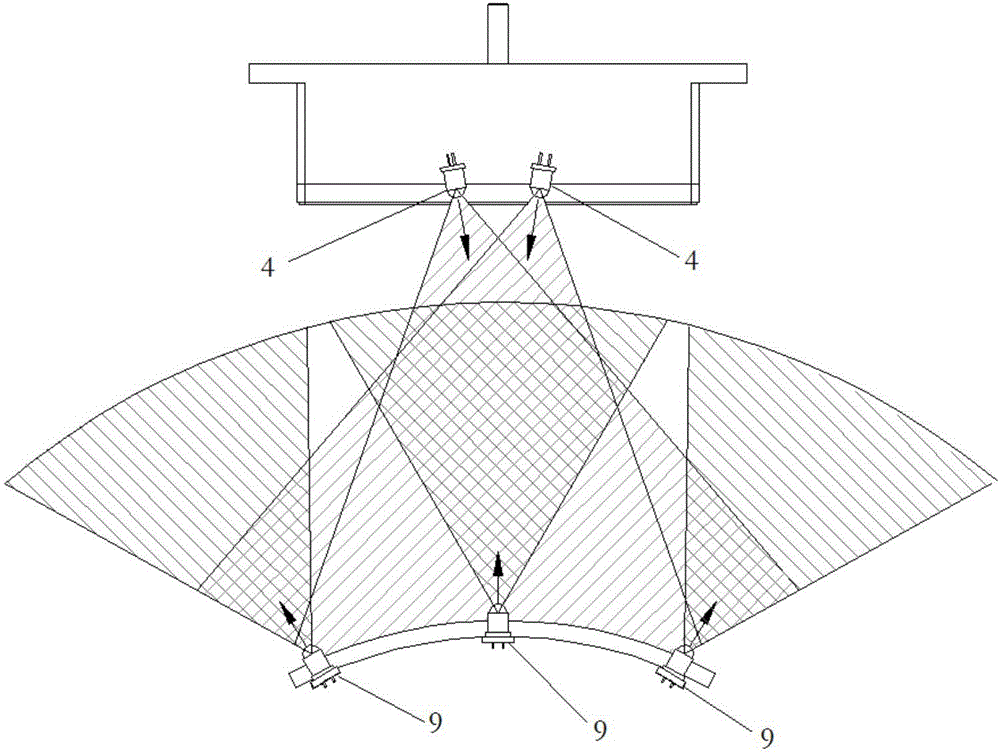
[0038] see figure 1 and figure 2 The robot automatic docking and charging system provided in this embodiment is used to automatically dock and charge the robot, including a robot and a charging pile. Two receiving infrared sensors 4 and robot control terminals, the charging pile includes a charging pile housing 13, a positive contact copper plate 5 of the charging pile, a charging insulating sleeve 6, a negative contact copper plate 7 of the charging pile, a guide sleeve 8, (2n+1) An infrared emission sensor 9, a baffle 10, a limit switch 11, a charging adapter 12 and a charging pile control terminal.

[0039] The positive contact copper plate 1 of the robot and the negative contact copper plate 3 of the robot are closely fitted and installed on the insulating sleeve 2, the insulating sleeve 2 is installed on the rear shell of the robot, and the two receiving infrared sensors 4 are installed on the adjust...

Embodiment 2

[0044] Embodiment 2. A method for automatic docking and charging of a robot.

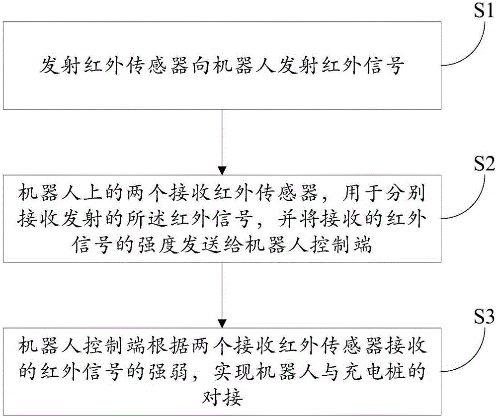
[0045] see image 3 In this embodiment, the method for realizing automatic docking and charging by using the robot automatic docking and charging system in the above-mentioned embodiment 1 includes:

[0046] (2n+1) transmitting infrared sensors on the charging pile transmit infrared signals to the robot, where n≥1, and n is a positive integer; two receiving infrared sensors on the robot are used to receive the emitted infrared signals respectively , and send the strength of the received infrared signal to the robot control terminal; the robot control terminal judges the deviation position of the robot car body according to the intensity of the infrared signals received by the two receiving infrared sensors, and drives the motor driver on the robot to drive the corresponding The motor adjusts the moving position of the robot body until the intensity of the infrared signals received by the two receiv...


PUM


Abstract

The invention discloses an automatic butt joint charging system and an automatic butt joint charging method for a robot. The automatic butt joint charging system for the robot comprises a robot and a charging pile, wherein the robot comprises a robot shell, a robot positive electrode contact copper plate, an insulated sleeve, a robot negative electrode contact copper plate, two receiving infrared sensors and a robot control end; the charging pile comprises a charging pile shell, a charging pile positive electrode contact copper plate, a charging insulated sleeve, a charging pile negative electrode contact copper plate, a guide sleeve, (2n+1) transmitting infrared sensors, a baffle, a limiting switch, a charging adapter and a charging pile control terminal. Through detesting the strength of infrared signals received by the receiving infrared sensors at different positions on the robot, automatic butt joint between the robot and the charging pile is realized, and compared with the existing mode in which the charging pile adopts a manual aerial plug for charging, manual operation is reduced, and automatic charging on the robot by the charging pile is realized.

Description

technical field [0001] The invention relates to the technical field of artificial intelligence, in particular to a robot automatic docking charging system and an automatic docking charging method. Background technique [0002] The existing charging piles use manual aerial charging for charging the robot. Manual charging is more troublesome. It is very inconvenient for people to plug in the charger in time when the robot is at low voltage inside the robot. The robot cannot be charged when it is not nearby. Contents of the invention [0003] In order to overcome the deficiencies and defects of the prior art, the present invention provides a robot automatic docking charging system and an automatic docking charging method. [0004] The technical scheme that the present invention solves the problems of the technologies described above is as follows: [0005] On the one hand, the present invention provides an automatic docking and charging system for a robot, which is used for...

Claims


Application Information

Patent Timeline
Patent Type & Authority Applications(China)
IPC IPC(8): H02J7/00H01R43/26G05D1/02
CPCG05D1/0242H01R43/26H02J7/00034H02J7/0045H02J7/0086
Inventor 刘江平李其茹
Owner BEIJING C&W ELECTRONICS GRP
Why Eureka
Try Eureka