
Movable point array solar connection type drying system

A technology for drying and moving points of solar energy, applied in the field of solar energy utilization, can solve the problems of low solar energy collection efficiency, large scale, increased load, etc., and achieve the effect of overcoming the low solar energy collection time, improving the utilization time and efficiency, and improving the tracking efficiency.

Inactive Publication Date: 2016-11-16
CHENGDU AONENGPU TECH
View PDF7 Cites 0 Cited by
  • Summary
  • Abstract
  • Description
  • Claims
  • Application Information

AI Technical Summary

Problems solved by technology

And the solar energy utilization equipment of existing dish technology moves with the change of the sunglasses, because the weight of large solar energy utilization equipment will increase the load, which is not conducive to tracking, so the existing dish technology needs to be improved
[0007] The tower system uses a solar mirror as a heliostat, and focuses multiple solar reflectors on a dryer. Due to the characteristics of tower solar energy collection, the utilization time of part of the solar mirror in the tracking solar process is only For example, the solar mirror on the east side of the tower is basically unusable in the morning, and can only be used after noon or afternoon, so the efficiency of solar energy collection is low. This technical solution can achieve high-temperature collection, but usually its scale is relatively small. Large, not suitable for small or home systems

Method used


Image

  • Movable point array solar connection type drying system
  • Movable point array solar connection type drying system
  • Movable point array solar connection type drying system

Examples


Embodiment 1

[0070] Embodiment 1: A mobile point array solar energy collection and utilization system composed of 4 solar mirrors and 2 solar energy utilization devices

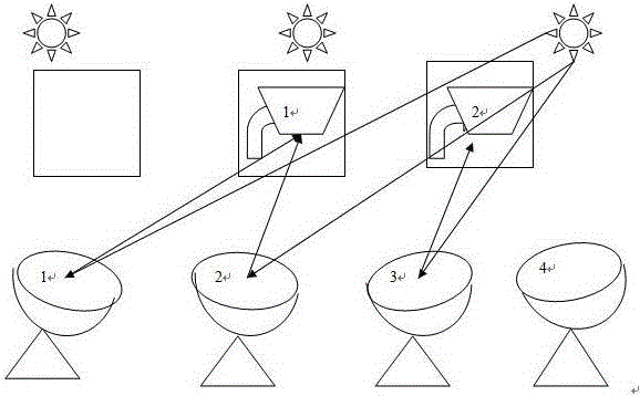
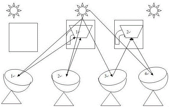
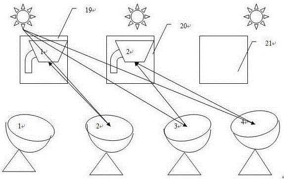
[0071] as attached figure 1 , 2 , 3 shows the moving point array solar collection and utilization system composed of 4 solar mirrors and 2 dryers, figure 1 , 2 , 3 are the collection and utilization of solar energy in the morning, noon and afternoon respectively, figure 1 In the morning, the sun rises from the east, and No. 1, 2 and 3 solar mirrors focus the solar energy on No. 1 and No. 2 dryers respectively to realize the tracking and focusing of solar energy; figure 2 At noon, the sun is located in the central area of ​​the sky. No. 1 and No. 2 solar mirrors focus the solar energy on the No. 1 dryer respectively, and No. 3 and No. 4 solar mirrors focus on the No. 2 solar storage device to realize the tracking and focusing of solar energy; image 3 In the afternoon, the sun falls in the west, 1 dryer moves from No....

Embodiment 2

[0072] Embodiment 2: A moving point array solar energy collection and utilization system composed of 12 solar mirrors and 6 solar energy utilization devices

[0073] This example Figure 4 The mobile point array solar collection and utilization system composed of 12 solar mirrors and 6 dryers is shown. The 12 solar mirrors are arranged in an array of three rows and four columns, and the six dryers are arranged in an array of three rows and two columns. Dryers are respectively arranged in the middle area of ​​the three rows of solar mirrors.

[0074]In different time periods in the morning, noon, and afternoon, solar mirrors 1-12 can choose different dryers 1-6 for focusing, and according to the actual solar energy collection efficiency, select different focus points for focusing, and are in different positions For solar mirrors No. 1-12, the choice of focusing dryers is also different. For No. 1, 5, 9, 4, 8, and 12 solar mirrors on both sides, there are 2 dryers that can be s...

Embodiment 3

[0077] Embodiment 3: 1*3 moving point solar energy tracking utilization system

[0078] as attached Figure 5 As shown, this embodiment adopts three parabolic dish solar mirrors (2), which are arranged on a parabolic connecting part, and each solar mirror is connected to the parabolic connecting part through a system axis, and the horizontal axis of the system axis The axis and the longitudinal axis are perpendicular to each other. This embodiment is a solar mirror bracket composed of three system axes arranged on the connecting parts. The connecting parts do not move, but the three system axes move. connection, set physical and optical sensors on each solar mirror (2), the solar tracking control device is an integrated electronic control device composed of motor, transmission gear and electronic control part, and adopts a tracking system that complements physical and optical tracking to realize tracking Solar energy tracking, at the same time, the dryer is equipped with a so...


PUM


Abstract

The invention relates to solar energy utilization, in particular to a movable point array solar connection type drying system. The movable point array solar connection type drying system at least comprises one point focusing solar mirror or one set of point focusing solar mirrors, at least one dryer and a tracking control device. The solar mirrors are arranged on solar mirror supports. The dryers are arranged on dryer supports. At least one of the solar mirrors or / and the corresponding solar mirror support is / are connected with the dryers. The solar mirrors and the dryers are made to move together through the tracking control device. The tracking control device controls the solar mirrors to focus sunlight to at least one dryer when the sunlight changes. The dryers move while the solar mirrors track the solar energy, each solar mirror or each set of solar mirrors select the dryer which can achieve the highest solar energy utilization efficiency for focusing, and thus tracking, focusing and utilization of solar energy are achieved.

Description

technical field [0001] The invention relates to the utilization of solar energy, in particular to the use of a point-focused solar mirror to realize solar energy collection, the use of solar point focus to realize a focus tracking dryer for solar energy, and the focus and utilization of solar energy. Background technique [0002] Solar drying is to use solar drying equipment to dry industrial and agricultural by-products. We call it solar drying. [0003] Drying equipment is also called dryer and dryer. The equipment used for drying operation, by heating the moisture in the material (generally refers to water or other volatile liquid components) to vaporize and escape, so as to obtain a solid material with a specified moisture content. The purpose of drying is to meet the needs of material use or further processing. For example, drying wood before making wooden molds and woodware can prevent product deformation, and drying ceramic blanks before calcination can prevent crac...

Claims


Application Information

Patent Timeline
Patent Type & Authority Applications(China)
IPC IPC(8): F26B3/28F24J2/00F24J2/38F24J2/40F24J2/46F24J2/54H02S20/32H02S40/42F24S20/30F24S50/20
CPCF26B3/28H02S20/32H02S40/42Y02E10/50
Inventor 李建民
Owner CHENGDU AONENGPU TECH
Learn More