A boiler blowing device

A technology for blowing device and boiler, applied in the field of boiler, can solve the problem of air intake at the bottom of incombustible materials, etc., and achieve the effects of effective air intake, low cost and simple structure

Active Publication Date: 2019-04-19
新昌县大船畈生物科技有限公司
View PDF5 Cites 0 Cited by
  • Summary
  • Abstract
  • Description
  • Claims
  • Application Information

AI Technical Summary

Problems solved by technology

[0002] The boiler is a kind of energy conversion equipment. The energy input to the boiler includes chemical energy and electric energy in the fuel, and the boiler outputs steam, high-temperature water or organic heat carrier with a certain amount of heat energy. At present, most of the fuels used by boilers are coal, gas, electricity , wood, etc. When using coal, wood, etc. as raw materials, the boiler combustion chamber must ensure sufficient air intake to ensure sufficient combustion. However, the existing air intake device is difficult to effectively intake air from the bottom of the combustion material.

Method used


Image

  • A boiler blowing device

Examples


Embodiment Construction

[0012] In order to make the purpose, technical solutions and advantages of the embodiments of the present invention clearer, a clear and complete description will be made below in conjunction with the technical solutions in the embodiments of the present invention. Obviously, the described embodiments are part of the embodiments of the present invention, and Not all examples. Based on the embodiments of the present invention, all other embodiments obtained by persons of ordinary skill in the art without making creative efforts belong to the protection scope of the present invention.

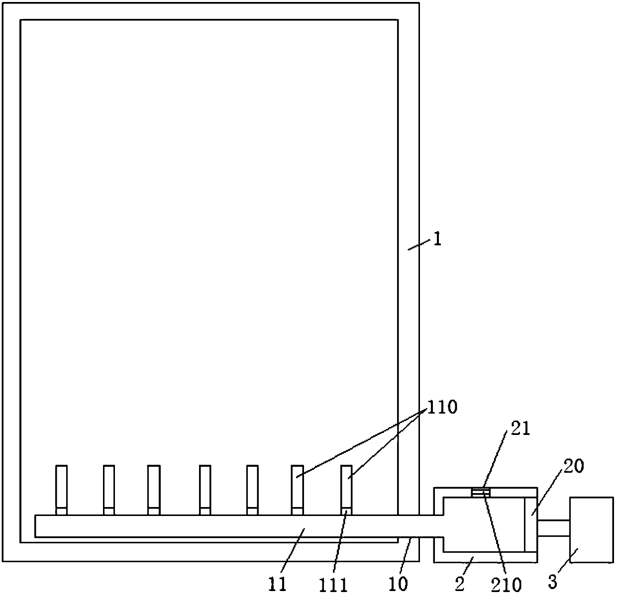
[0013] The boiler blast device of the preferred embodiment of the present invention is as figure 1 As shown, it includes a combustion chamber 1, and the lower part of the side wall of the combustion chamber 1 is provided with a first air inlet hole 10 communicating with the interior thereof; it also includes a first air inlet duct 11 cooperating with the first air inlet hole 10, and the first air...


PUM


Abstract

The invention relates to a blower device for a boiler. The blower device comprises a combustion chamber. A first wind inlet hole is formed in the lower portion of the side wall of the combustion chamber. The blower device further comprises a first wind inlet pipeline matched with the first wind inlet hole. One end of the first wind inlet pipeline extends into the bottom in the combustion chamber, and the end is sealed. Multiple air outlet pipes are arranged on the side wall of the first wind inlet pipeline in a connected manner. A first one-way air inlet valve is arranged on the position, connected with the first wind inlet pipeline, of each air outlet pipe. A second wind inlet pipeline is arranged at the other end of the first wind inlet pipeline in a communicating manner. A piston is arranged in the second wind inlet pipeline, and a second wind inlet hole is formed in the side wall of the second wind inlet pipeline. A second one-way air inlet valve is arranged in the second wind inlet hole. The blower device further comprises a drive air cylinder. When the piston is driven through the drive air cylinder to move outwards, the first one-way air inlet valve is closed, the second one-way air inlet valve is opened, air in the outside enters the first wind inlet pipeline and the second wind inlet pipeline, then the air cylinder is driven to drive the piston to move inwards, the first one-way air inlet valve is opened, the second one-way air inlet valve is closed, air entering the blower device is discharged into the lower portion of a combustible of the combustion chamber through the air outlet pipes.

Description

technical field [0001] The invention relates to the technical field of boilers, and more specifically, relates to a boiler blower device. Background technique [0002] The boiler is a kind of energy conversion equipment. The energy input to the boiler includes chemical energy and electric energy in the fuel, and the boiler outputs steam, high-temperature water or organic heat carrier with a certain amount of heat energy. At present, most of the fuels used by boilers are coal, gas, electricity, etc. , wood, etc. When using coal, wood, etc. as raw materials, the boiler combustion chamber must ensure sufficient air intake to ensure sufficient combustion. However, the existing air intake device is difficult to effectively intake air from the bottom of the combustion material. Contents of the invention [0003] The technical problem to be solved by the present invention is to provide a boiler blower device with simple structure, low cost and effective air intake for the above-m...

Claims


Application Information

Patent Timeline
Patent Type & Authority Patents(China)
IPC IPC(8): F23L1/02F23L3/00
CPCF23L1/02F23L3/00
Inventor 吴鹏
Owner 新昌县大船畈生物科技有限公司
Why Eureka
Try Eureka