Recycling pool of muddy water

A technology of water recycling and cement slurry, which is applied in cement mixing devices, flocculation/sedimentation water/sewage treatment, settling tanks, etc., can solve the problems of unfavorable comprehensive utilization of cement slurry water, etc., and achieve the effect of reducing operating costs

Inactive Publication Date: 2016-11-16
王金龙
View PDF5 Cites 1 Cited by
  • Summary
  • Abstract
  • Description
  • Claims
  • Application Information

AI Technical Summary

Problems solved by technology

[0004] The purpose of the present invention is to solve the problem that the traditional cement slurry water mixing tank and sedimentation tank are set separately, which is not conducive to the comprehensive utilization of cement slurry water, and to provide a cement slurry water recovery tank

Method used


Image

  • Recycling pool of muddy water
  • Recycling pool of muddy water

Examples


Embodiment

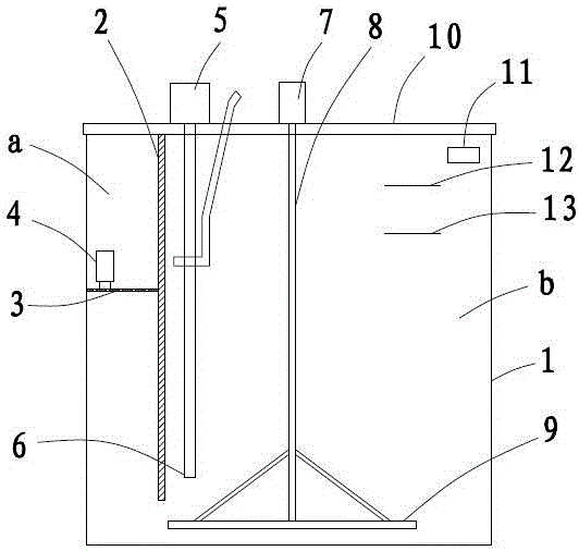
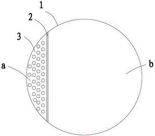
[0021] Embodiment: a kind of cement slurry water recovery pond, as figure 1 shown. The device comprises a circular pool body 1, the pool wall and the pool bottom of which are made of steel plates. Such as figure 1 , 2 As shown, one side of the pool is provided with a vertical partition 2, and the partition divides the pool into a sedimentation zone a and a stirring zone b. The volume of the stirring zone b is 6-8 times the area of ​​the precipitation zone a. There is a gap between the bottom end of the partition and the bottom surface of the tank body, so that the sedimentation zone and the stirring zone are connected to each other at the bottom.

[0022] A horizontal orifice plate 3 is provided at the waist of the sedimentation area a, and a cleaning water pump 4 is provided above the horizontal orifice plate 3 . The horizontal orifice plate separates the sedimentation area up and down to ensure that the upper water body is still and accelerate the sedimentation. The cl...


PUM


Abstract

The invention relates to a recycling pool of muddy water, and solves the problem that the comprehensive utilization of muddy water is not facilitated due to the fact that a traditional muddy water stirring tank and a sedimentation tank are separately arranged. The device comprises a pool body, and is characterized in that a vertical partition is arranged on one side of the pool body; the top of the partition is higher than the highest water line of the pool body; a circulation clearance which communicates with the two sides of the partition is arranged between the bottom of the partition and the bottom surface of the pool body; one side of the partition is a sediment zone; a horizontal pore plate is arranged at the middle part of the vertical direction of the sediment zone; the other side of the partition is a stirring zone; and a stirrer driven by a motor and a slurry pump for pumping turbid muddy water are arranged in the stirring zone. According to the recycling pool, after recycling, the muddy water is utilized in multiple ways, mud in the pool body of the device is continuously stirred and is pumped by the slurry pump for concrete stirring, extra desilting is not needed, and the operation cost is reduced.

Description

technical field [0001] The invention belongs to the field of engineering construction, in particular to a cement slurry water recovery tank. Background technique [0002] During the construction of the construction site, a large amount of cement slurry water will be produced. Traditionally, there are generally two destinations for the cement slurry water. One is to discharge the cement slurry water into the sedimentation tank. After one or more stages of sedimentation, relatively clear water is obtained, which is used for washing concrete tank trucks, etc. Or reuse it for concrete mixing. This treatment method will accumulate a large amount of sludge at the bottom of the sedimentation tank, which needs to be cleaned regularly, which will increase the cost of cleaning; the second is to discharge the cement slurry water into the mixing tank, and use the mixer in the mixing tank to continue stirring , to keep the slurry in motion and reduce sedimentation. In this way, the turb...

Claims


Application Information

Patent Timeline
IPC IPC(8): B28C5/16B28C5/08B01D21/02C02F1/52
CPCB01D21/0018B01D21/02B28C5/0806B28C5/16C02F1/52
Inventor 王金龙
Owner 王金龙
Why Eureka
Try Eureka