
Crank throw positioning clamp

A technology for positioning fixtures and cranks, which is applied in the direction of expanding mandrels, etc., can solve the problems affecting machining accuracy, machining efficiency, machining safety, inconsistent crank arm clamping force F, and large dimensional errors, which is conducive to automated production, The effect of reducing impact damage and high work efficiency

Active Publication Date: 2016-11-16
CHONGQING MEIXIN YINGSHEN MACHINERY CO LTD
View PDF9 Cites 0 Cited by
  • Summary
  • Abstract
  • Description
  • Claims
  • Application Information

AI Technical Summary

Problems solved by technology

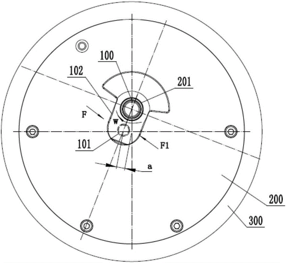
and figure 2 Then it is the defect that exists as the prior art, that is, the clamping force F on both sides of the crank arm (102) is inconsistent or the uneven force generated by the main journal (100) after positioning produces a torque W, and the connecting rod journal (101) and The spindle disc (300) is no longer coaxial but has a certain eccentricity
And existing fixture is positioned after crank arm (102) clamping location and main journal (100) location, all exists figure 2 The problem of inconsistency between F and middle F, and the need to calibrate and check after each clamping, there are defects such as complicated operation, long auxiliary time and uncontrollable precision; and in the high-speed fine turning of the crank throw, the crank throw is not uniform due to eccentric force. Vibration leads to large dimensional errors after processing, seriously affecting processing accuracy, processing efficiency and processing safety

Method used


Image

  • Crank throw positioning clamp
  • Crank throw positioning clamp
  • Crank throw positioning clamp

Examples


Embodiment Construction

[0037] Below in conjunction with accompanying drawing and embodiment the present invention will be further described:

[0038] see Figure 4 , a bellcrank positioning fixture, including a positioning plate 1, a push rod 2, a taper sleeve 3, a spring jacket 4, a pair of positioning arms 5, a push plate 6, a retaining ring 7, a telescopic cylinder 8 and a connecting assembly 9.

[0039] combine Figure 4-5, wherein a first positioning hole 11 , a second positioning hole 12 and a mounting hole are opened in parallel on the positioning plate 1 , and the positioning plate 1 is installed on the outside of the connecting assembly 9 .

[0040] see Figure 4 , wherein, the ejector rod 2 is installed in the second positioning hole 12 with clearance fit, the outer end of the ejector rod 2 is provided with a tapered portion 21, and the inner end thereof passes through the second positioning hole 12 and is aligned with the pushing rod 2. Plates 6 are connected vertically.

[0041] comb...


PUM


Abstract

The invention discloses a crank throw positioning clamp. The crank throw positioning clamp is characterized by comprising a positioning plate, an ejection rod, a taper sleeve, a spring clamping sleeve and a pair of positioning rotary arms. The positioning plate is provided with a first positioning hole and a second positioning hole in parallel; the taper sleeve is installed in the first positioning hole; the ejection rod is installed in the second positioning hole; the spring clamping sleeve is installed in the taper sleeve, and the outer taper face of the spring clamping sleeve is matched with an inner taper hole of the taper sleeve; a stopping ring is arranged on the outer side of the spring clamping sleeve; the positioning rotary arms are symmetrically arranged along the center connecting line of the first positioning hole and the second positioning hole, and the middle portions of the positioning rotary arms are both hinged to the outer side face of the positioning plate; the outer end of the ejection rod is provided with a taper part, a gap exists between the first ends of the pair of positioning rotary arms, and the second ends of the pair of positioning rotary arms are located on the two sides of the spring clamping sleeve. By means of the crank throw positioning clamp, accurate positioning can be achieved, and eccentricity is not prone to occurrence.

Description

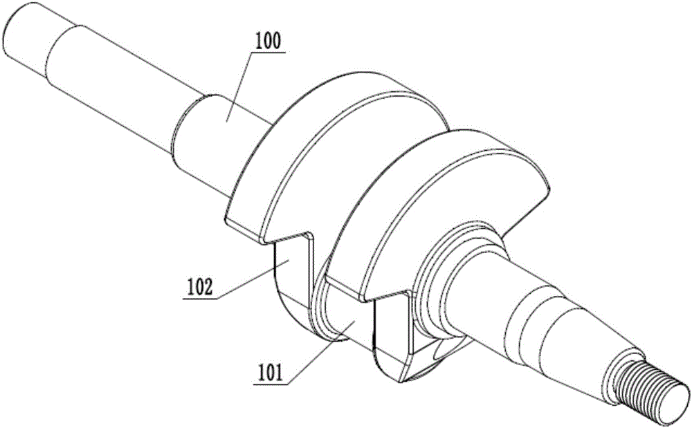
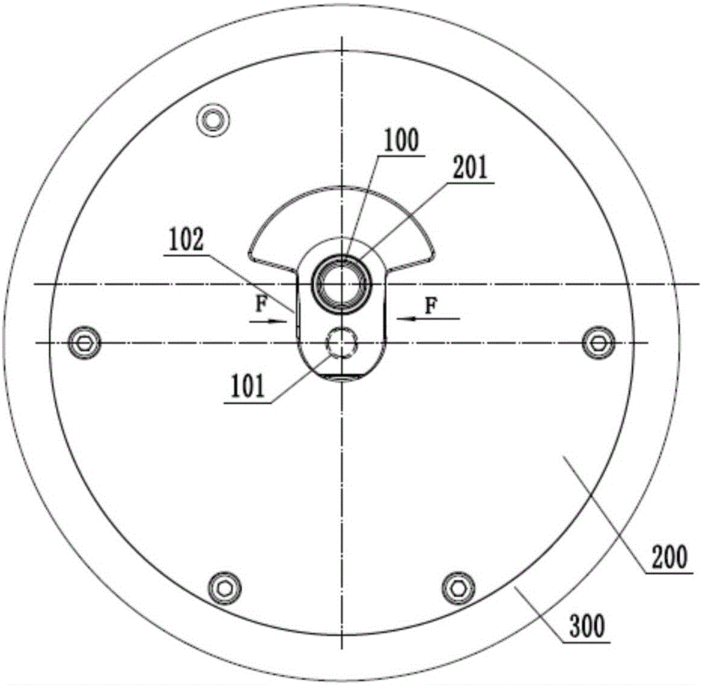
technical field [0001] The invention relates to a crank throw positioning fixture. Background technique [0002] The crankshaft is composed of a connecting rod journal (crank pin), two left and right crank arms and two left and right main journals, and the crankshaft is composed of several crankshafts. [0003] To illustrate the problems with existing fixtures, see Figure 1-3 , the connecting rod journal on the crank throw is fixed on the main shaft disc (300) of the machine tool through the positioning disc (200) of the fixture, and the positioning disc (200) is provided with a main journal positioning hole (201 ), and a certain distance is eccentric between the center of the main journal positioning hole (201) and the axis of the main shaft disc (300). After the crank throw is positioned, it needs to meet: first, the connecting rod journal (101) of the crank throw is coaxial with the main shaft disc (300) and cannot move axially; second: the crank arm (102) positioning c...

Claims


Application Information

Patent Timeline
Patent Type & Authority Applications(China)
IPC IPC(8): B23B31/40
CPCB23B31/4006
Inventor 余洪徐争鸣周勇蔡吉良谢昌国
Owner CHONGQING MEIXIN YINGSHEN MACHINERY CO LTD
Learn More