Light-emitting display with straight and parallel fork gate-controlled mouth, sharp triangle top-type cathode structure and its manufacturing process

A technology of luminescent display and cathode structure, applied in cathode ray/electron beam tube fluorescent screen, image/graphic display tube, cathode ray tube/electron beam tube, etc., can solve the problem of reducing the luminous brightness and luminous intensity of luminescent display The effective emission area is small, the gate current is too large, etc., to achieve the effect of reducing the effective distance, reducing useless power loss, and reducing the working voltage

Active Publication Date: 2017-08-04
阜阳市战千里知识产权运营有限公司
View PDF5 Cites 0 Cited by
  • Summary
  • Abstract
  • Description
  • Claims
  • Application Information

AI Technical Summary

Problems solved by technology

Second, the effective emission area of ​​carbon nanotubes is too small
Third, the problem of excessive gate current is also prominent
However, if the gate current is too large, it means that the number of field emission electrons trapped by the gate is too large, which will greatly reduce the luminous brightness and luminous intensity of the light-emitting display.

Method used


Image

  • Light-emitting display with straight and parallel fork gate-controlled mouth, sharp triangle top-type cathode structure and its manufacturing process
  • Light-emitting display with straight and parallel fork gate-controlled mouth, sharp triangle top-type cathode structure and its manufacturing process
  • Light-emitting display with straight and parallel fork gate-controlled mouth, sharp triangle top-type cathode structure and its manufacturing process

Examples


Embodiment Construction

[0043] The present invention will be further described below in conjunction with the accompanying drawings and embodiments, but the present invention is not limited to this embodiment.

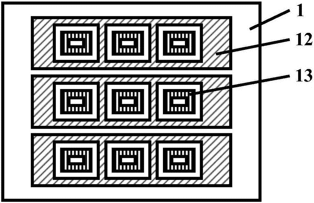
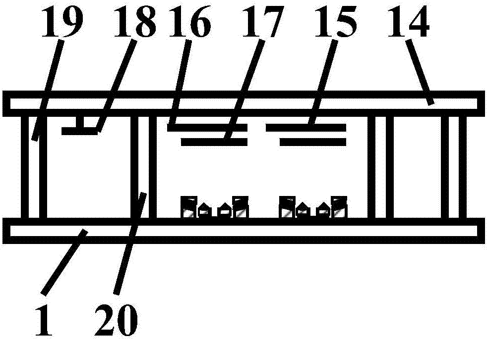
[0044] The light-emitting display of the oblique straight parallel fork gated mouth word pointy triangular top type cathode structure of the implementation is as follows figure 1 , figure 2 and image 3 Shown, comprise the vacuum chamber that is made of cathode encapsulation plate 1, anode encapsulation plate 14 and transparent glass frame 19; On anode encapsulation plate 14, anode conduction layer 15, phosphor layer 17 prepared on anode conduction layer 15 and The anode extension line layer 16 connected to the anode conductive layer 15; there is an oblique straight parallel fork gate control mouth pointed triangle top cathode structure on the cathode packaging plate 1; the support column 20 and the getter 18 auxiliary components located in the vacuum chamber.

[0045] Among them, the obliq...


PUM


Abstract

The invention discloses a light-emitting display with an inclined parallel crossed gating square pointed triangular roof-type cathode structure, and the display comprises a vacuum chamber which consists of a cathode packaging plate, an anode packaging plate and a transparent glass frame. The anode packaging plate is provided with an anode conducting layer, a fluorescent powder layer prepared on the anode conducting layer, and an anode external extending line layer connected with the anode conducting layer. The cathode packaging plate is provided with an inclined parallel crossed gating square pointed triangular roof-type cathode structure. The display also comprises a supporting column located in the vacuum chamber, and a getter attaching element. The display is simple and feasible, is high in light brightness, and is high in finished rate.

Description

technical field [0001] The present invention belongs to the fields of vacuum science and technology, optoelectronic science and technology, integrated circuit science and technology, display technology, microelectronics science and technology and nano science and technology, and relates to a flat field emission display The manufacture specifically relates to the manufacture of a planar field emission luminescent display of a carbon nanotube cathode, in particular to a luminescent display with a slanted straight parallel fork-gated mouth-pointed triangular-top cathode structure and its manufacturing process. Background technique [0002] Carbon nanotubes are a new type of tubular objects with a diameter of about tens of nanometers; under the action of a sufficiently large external electric field, carbon nanotubes will emit a large number of electrons without applying other energy, forming a unique cold field Therefore, carbon nanotubes are also an excellent cold cathode mater...

Claims


Application Information

Patent Timeline
Patent Type & Authority Patents(China)
IPC IPC(8): H01J29/04H01J31/12
CPCH01J29/04H01J31/12H01J2229/18
Inventor 李玉魁
Owner 阜阳市战千里知识产权运营有限公司
Why Eureka
Try Eureka