
Fiber Optic Orientation Sensor for Partial Discharge Detection in High Voltage Electrical Equipment

A technology for partial discharge detection and high-voltage electrical equipment, which is applied in the field of sensors, can solve the problems of high sensor precision requirements, large influence of temperature changes, ultrasonic signal attenuation, etc., and achieve strong anti-interference ability, high sensitivity, and sensitive measurement effects

Active Publication Date: 2019-01-15
NORTH CHINA ELECTRIC POWER UNIV (BAODING)
View PDF5 Cites 0 Cited by
  • Summary
  • Abstract
  • Description
  • Claims
  • Application Information

AI Technical Summary

Problems solved by technology

The direct detection of visible light method is only suitable for high-voltage electrical equipment with transparent dielectrics as insulating materials, not suitable for partial discharge detection of high-voltage electrical equipment with solid dielectrics and liquid dielectrics as insulating materials; optical-ultrasonic sensors have strong anti-interference ability, Good insulation performance and other advantages, but it has high sensor precision requirements, difficult processing, and is greatly affected by temperature changes, and ultrasonic signals have more refraction and reflection and serious attenuation. It is suitable for partial discharge detection of fixed-shaped high-voltage electrical equipment, benefiting from the development of optical fiber technology, and has good application prospects

Method used


Image

  • Fiber Optic Orientation Sensor for Partial Discharge Detection in High Voltage Electrical Equipment
  • Fiber Optic Orientation Sensor for Partial Discharge Detection in High Voltage Electrical Equipment
  • Fiber Optic Orientation Sensor for Partial Discharge Detection in High Voltage Electrical Equipment

Examples


Embodiment Construction

[0020] The implementation will be described in detail below in conjunction with the accompanying drawings.

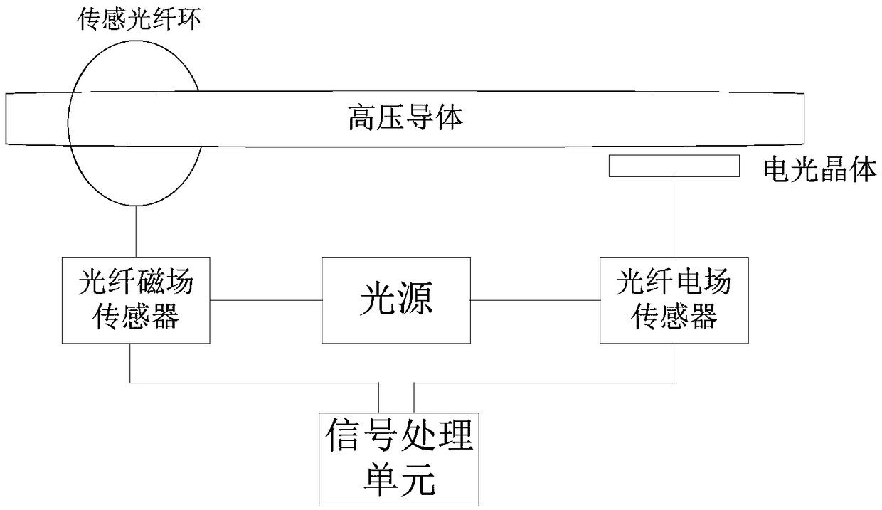
[0021] A fiber optic direction sensor for on-line partial discharge detection of high-voltage electrical equipment. The sensor system is composed of a fiber optic magnetic field sensor and a fiber optic electric field sensor. The propagation direction of the measured partial discharge signal is judged through joint detection.

[0022] Fiber optic magnetic field sensors such as figure 1 As shown, it includes: a first single-mode optical fiber, a first polarizer, a sensing fiber ring, a first analyzer, and a first photodetector.

[0023] Fiber optic electric field sensors such as figure 2 As shown, it includes: the second single-mode fiber, the first collimating lens, the second polarizer, the quarter wave plate, the electro-optic crystal, the second analyzer, the second collimating lens, and the second photodetector .

[0024] Both the first single-mode fiber and the...


PUM


Abstract

The invention belongs to the sensor technical field and relates to an optical fiber direction sensor for partial discharge detection of high-voltage electrical equipment. The optical fiber direction sensor includes an optical fiber magnetic field sensor and an optical electric field sensor; the optical fiber magnetic field sensor includes a first single-mode optical fiber, a first polarizer, an optical fiber sensing ring, a first analyzer and a first photoelectric detector which are connected with one another sequentially; the optical electric field sensor includes a second single-mode fiber, a first collimating lens, a second polarizer, a quarter-wave plate, an electro-optical crystal, a second analyzer, a second collimating lens and a second photoelectric detector which are connected with one another sequentially; the first single-mode optical fiber and the second single-mode optical fiber are both connected with a light source; the first photoelectric detector and the second photoelectric detector are both connected with a signal processing unit; and the signal processing unit judges the transmission direction of pulse signals through the polarity of the magnetic field and electric field of the pulse signals detected by the optical fiber magnetic field sensor and the optical electric field sensor.

Description

technical field [0001] The invention belongs to the technical field of sensors, in particular to an optical fiber direction sensor used for partial discharge detection of high-voltage electrical equipment. Background technique [0002] At present, there are many methods for on-line partial discharge monitoring of large-scale power equipment such as transformers and GIS at home and abroad, mainly including very high frequency (VHF) pulse current detection method, ultra high frequency (UHF) electromagnetic wave detection method and piezoelectric sensor ultrasonic detection method Among them, the VHF and UHF detection methods detect electrical signals, which are easily interfered by electromagnetic interference signals; the piezoelectric ultrasonic method detects ultrasonic signals, but the sensor is attached to the device shell to detect the ultrasonic signals generated by partial discharge inside the device. Although less susceptible to electromagnetic noise, it is not very s...

Claims


Application Information

Patent Timeline
Patent Type & Authority Patents(China)
IPC IPC(8): G01R31/12
CPCG01R31/1218
Inventor 王伟高超飞刘晗商超刘旭
Owner NORTH CHINA ELECTRIC POWER UNIV (BAODING)
Learn More