


Quick Research
Generate reliable direction feasibility study reports for your R&D in just a few steps.

Technical Q&A
Discover and master advanced knowledge NOW. Basics, ideas, possibilities, all at once.

Find Solutions
As an expert in R&D theories, this can generate solutions to your technical problems instantly.

Evaluate Feasibility
Analyze your overall solution with one click, know your potential R&D risks in advance.

Monitor Landscape
Get weekly tech updates, stay abreast of the latest tech innovations and key insights.
Optical analysis apparatus and method of gas
A light source and light collimation technology, applied in the field of photoelectric analysis, can solve problems such as poor beam collimation effect, poor optical interference noise suppression ability, aberration, etc., to reduce adverse effects, suppress optical interference noise, and reduce light source cost Effect
- Summary
- Abstract
- Description
- Claims
- Application Information
AI Technical Summary
Problems solved by technology
Method used
Image

Examples
Embodiment 1
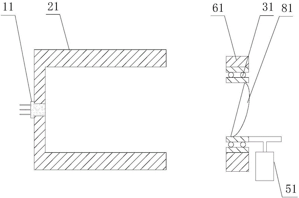
[0044] figure 1 Schematically provides a structural diagram of the novel light source of this embodiment, as figure 1 As shown, the novel light source includes:
[0045] The luminous body 11 is used to emit monochromatic light; the luminous body is fixed on the first bracket;
[0046] The first bracket 21, such as a circular sleeve, a mounting plate, etc., the bracket is used to carry the illuminant, and the bracket is formed with an optical channel suitable for the passage of the emitted light of the illuminant;
[0047] Light collimating device 81, such as plano-convex lens, described light collimating device is fixed on the optical path of the outgoing light of described illuminant, collimates described outgoing light; The axis of described light collimating device and described outgoing light The angle between the optical axes is an acute angle, such as 2 degrees, 10 degrees, 25 degrees, etc., but not more than 30 degrees;
[0048] Rotating member 31, the optical collim...
Embodiment 2
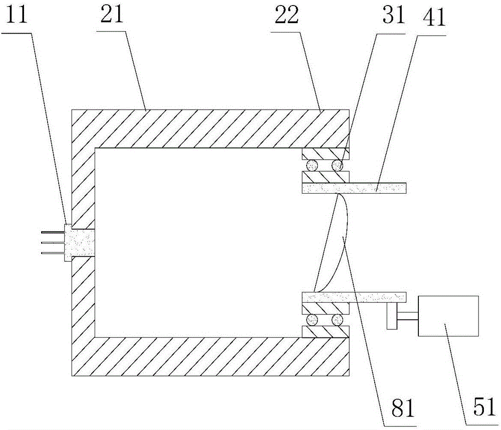
[0052] The laser gas analyzer of the embodiment of the present invention, the laser gas analyzer comprises:
[0053] new light sources, such as figure 2 As shown, the novel light source includes:
[0054] The illuminant 11 is a tunable semiconductor laser;
[0055] The first bracket 21 adopts a circular sleeve with a radial part and an axial part, and the illuminant is fixed at the center of the radial part; the part 22 of the axial part is used as the second bracket;
[0056] The rotating member 31 adopts a bearing, and the outer ring of the bearing is fixed on the second bracket, that is, the inner side of the axial part;
[0057] The fixing part 41, the fixing part adopts a sleeve, and is fixed on the rotating part, that is, on the inner ring of the bearing;
[0058] The optical collimation device 81 adopts a plano-convex lens, and the lens is fixed in the fixture, and the angle between the axis of the lens and the optical axis of the measuring light emitted by the lase...
Embodiment 3
[0068] The laser gas analyzer of the embodiment of the present invention, such as figure 1 Shown, different from embodiment 2 is:
[0069] 1. Fixing parts are no longer used, and the optical collimation device is directly fixed on the inner ring of the bearing. The motor directly drives the inner ring to rotate, and the driving wheel of the motor drives the inner ring by friction;
[0070] 2. The second bracket is set separately, and the outer ring of the bearing is fixed on the second bracket; the measurement light emitted by the laser passes through the optical collimation device, and the angle between the optical axis and the axis of the optical collimation device is Acute angles, such as 10 degrees, 15 degrees, 20 degrees, 30 degrees, etc.
[0071] The above-mentioned embodiments are only exemplified that the illuminants are lasers, and of course other illuminants, such as LEDs, may also be used.
PUM
| Property | Measurement | Unit |
|---|---|---|
| Acute angle | aaaaa | aaaaa |
Abstract
Description
Claims
Application Information
 - R&D Engineer
- R&D Manager
- IP Professional
- Industry Leading Data Capabilities
- Powerful AI technology
- Patent DNA Extraction
Browse by: Latest US Patents, China's latest patents, Technical Efficacy Thesaurus, Application Domain, Technology Topic, Popular Technical Reports.
© 2024 PatSnap. All rights reserved.Legal|Privacy policy|Modern Slavery Act Transparency Statement|Sitemap|About US| Contact US: help@patsnap.com