
Combined thermal shock testing system and method in lasting gradient temperature field

A gradient temperature and experimental system technology, applied in the field of heat treatment, can solve problems such as the inability to form a gradient temperature field, the inability to meet the thermal shock experiment requirements of a persistent gradient temperature field, and the difficulty in simulating the service environment of hot-end components.

Active Publication Date: 2016-11-09
XI AN JIAOTONG UNIV
View PDF6 Cites 16 Cited by
  • Summary
  • Abstract
  • Description
  • Claims
  • Application Information

AI Technical Summary

Problems solved by technology

However, the existing two types of mainstream high-temperature experimental systems cannot meet the requirements of thermal shock experiments with persistent gradient temperature fields: first, the high-temperature test equipment represented by oxidation furnaces can provide long-term uniform temperature fields, and can realize thermal shock after further modification. impact, but it cannot form a gradient temperature field, and it is difficult to simulate the actual service environment of the hot-end components; second, the high-temperature test equipment represented by the gas thermal shock system can simulate the thermal shock under the gradient temperature field, but it is limited to extremely high operating costs and is not suitable for To provide a persistent gradient temperature field
In addition, high temperature experiments are more dangerous, and it is not suitable for too much intervention by experimenters, and automatic control of the system needs to be realized

Method used


Image

  • Combined thermal shock testing system and method in lasting gradient temperature field
  • Combined thermal shock testing system and method in lasting gradient temperature field
  • Combined thermal shock testing system and method in lasting gradient temperature field

Examples


Embodiment Construction

[0030] The present invention will be further described below in conjunction with accompanying drawing and specific embodiment:

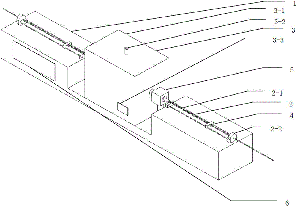
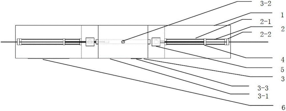
[0031] Such as Figure 1~4 As shown, a combined thermal shock experiment system under a persistent gradient temperature field of the present invention includes a frame 1, a displacement module 2, a heating module 3, an internal cooling module 4, an external cooling module 5, and a measurement and control module 6; wherein, the machine Frame 1 is covered with aluminum alloy plate including but not limited to aluminum alloy truss structure to provide support for the experimental system; displacement module 2 is fixed on the frame 1, including guide rail 2-1 to limit the directional displacement of the specimen, and including but not limited to step The actuating mechanism 2-2 of the feeding motor accurately controls the displacement of the specimen; the heating module 3 is fixed on the frame 1 by including but not limited to a high-temperature tube furn...


PUM


Abstract

The invention discloses a combined thermal shock testing system and method in a lasting gradient temperature field. The testing system comprises a frame, a displacement module, a heating module, an internal cooling module, an external cooling module, and a measuring and controlling module, wherein the frame and the displacement module bear a test piece coming in and going out from the heating module and the external cooling module; the heating module provides a lasting high-temperature environment for oxidation-sintering-phase change testing; the internal cooling module and the heating module cooperate with each other to form a gradient temperature field along the thickness direction of the test piece so as to simulate actual service conditions; the external cooling module carries out rapid cooling on the test piece to complete thermal shock; and the measuring and controlling module acquires testing parameters like temperature and flow velocity and regulates and controls cooperative operation of each module. The invention provides the economic, safe and reliable combined thermal shock testing system and method in the lasting gradient temperature field, and parameters can be set to realize experiments including, but not limited to, conventional thermal cycle / shock, gradient temperature field oxidation / sintering, isothermal oxidation / sintering, etc.

Description

Technical field: [0001] The invention belongs to the field of heat treatment, and relates to heat treatment of a test piece under a cyclic gradient temperature field, in particular to a combined thermal shock experiment system and method under a persistent gradient temperature field. Background technique: [0002] In many modern industrial fields such as aerospace, energy, and electric power, hot-end components often work in complex temperature fields, especially gradient temperature fields where one side is heated and the other side is cooled; But it is not limited to the thermal shock caused by start-up and shutdown; a series of processes such as oxidation-sintering-phase transformation caused by long-term high-temperature environment will lead to the degradation of the mechanical and thermal properties of the hot-end components. Therefore, it is very important to study the performance and life of the hot end components under the action of thermal shock in the persistent g...

Claims


Application Information

Patent Timeline
IPC IPC(8): G01N3/60
CPCG01N3/60G01N2203/0222
Inventor 王铁军吕伯文李定骏范学领
Owner XI AN JIAOTONG UNIV
Learn More