System for measuring time-resolved flow processes of fluids

A time-resolved, fluid-based technology that is applied in measuring flow/mass flow, detecting fluid flow by measuring differential pressure, and measuring capacity. It can solve problems such as viscosity or density fluctuations, and achieve the effect of eliminating influence and avoiding erroneous measurements.

Active Publication Date: 2021-04-20
AVL列表有限责任公司
View PDF16 Cites 0 Cited by
  • Summary
  • Abstract
  • Description
  • Claims
  • Application Information

AI Technical Summary

Problems solved by technology

[0005] However, it turns out that the determination of the injection quantity curve can also be erroneously caused by hitherto unappreciated fluctuations in the viscosity or density of the measured fluid

Method used


Image

  • System for measuring time-resolved flow processes of fluids
  • System for measuring time-resolved flow processes of fluids

Examples


Embodiment Construction

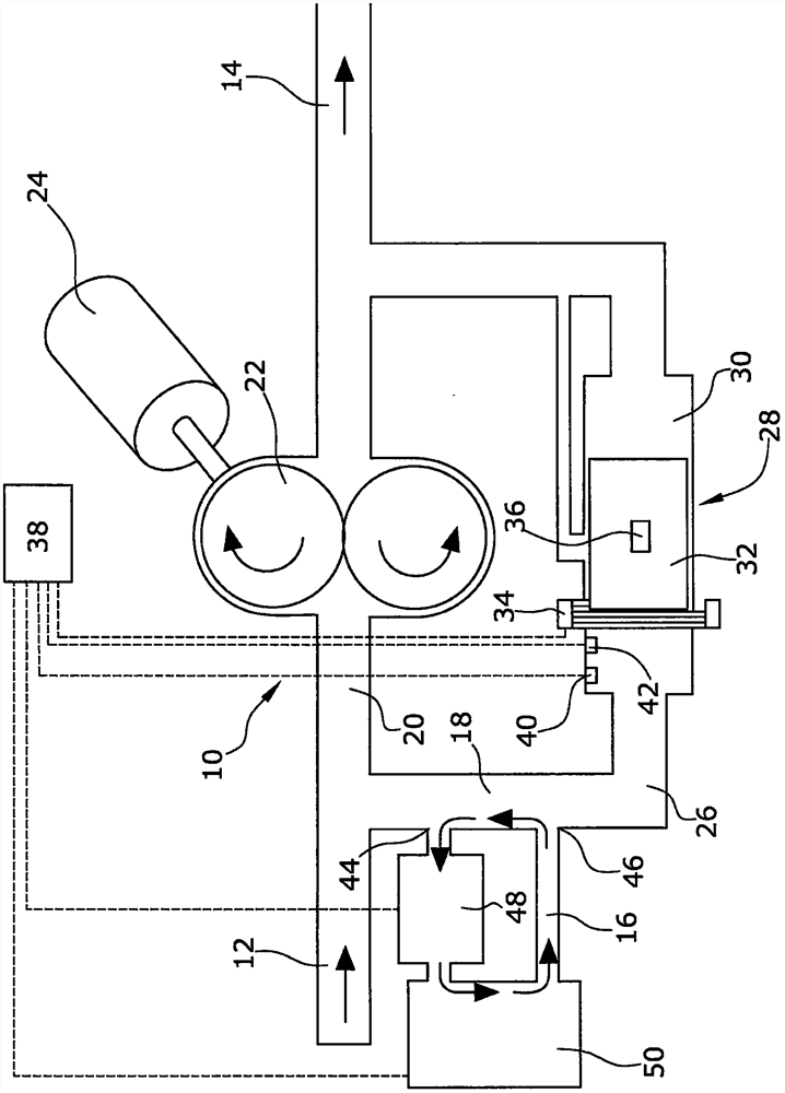
[0026] exist figure 1 The system according to the invention for measuring the time-resolved flow process of a fluid shown in , consists of a flow meter 10 with an inlet 12 and an outlet 14 and a bypass line 16 through which the flow meter 10 can be bypassed. Pipe section 18 .

[0027] Via inlet 12 , the fluid to be measured, in particular fuel, flows from a flow-generating device, in particular a high-pressure fuel pump and at least one injection valve, into main line 20 of flow meter 10 . A rotary extruder 22 in the form of a double gear pump is arranged in this main conduit 20 . Downstream from the extruder 22 , the main conduit 20 ends at the outlet 14 . The gear pump 22 is driven by a drive motor 24 through a clutch or a transmission.

[0028]From the main pipe 20, a detour pipe 26 is branched between the inlet 12 and the rotating extruder 22, and the detour pipe follows the downstream flow of the rotating extruder 22 and then merges into the main pipe 20 between the ex...


PUM


Abstract

The invention relates to a system for measuring a time-resolved flow process of a fluid having an inlet (12), an outlet (14) and a flow meter (10) arranged between the inlet (12) and the outlet (14). In order to be able to provide the usual other parameters in addition to the chemical and physical state of the fluid being conveyed, it is proposed that the pipe section (18) of the flow meter (10) can be bypassed by a bypass pipe (16) in which it is connected in series A pump (48) and a sensor (50) for measuring the physical or chemical properties of the fluid being delivered are provided.

Description

technical field [0001] The invention relates to a time-resolved A system for the flow process of a fluid having an inlet, an outlet, and a flow meter arranged between the inlet and the outlet, and also relates to a system for measuring a time-resolved flow process of a fluid, having an inlet, an outlet (the outlet passes through a main pipe and Inlet flow connection), a driven extruder placed in the main pipe, a detour pipe (the detour pipe branches from the main pipe between the inlet and the extruder, and merges into the main pipe between the extruder and the outlet pipeline), a differential pressure recorder (which is set in the circuitous pipeline), and a value and control unit through which the actuated squeezer can be adjusted according to the pressure difference on the linear differential pressure recorder. compressor. Background technique [0002] Systems of this type have been known for many years and are used, for example, for fuel injection measurements on inte...

Claims


Application Information

Patent Timeline
Patent Type & Authority Patents(China)
IPC IPC(8): G01F1/34
CPCF02M65/00G01F3/16G01F15/02G01F1/34G01F1/50G01F3/10G01F5/005G01F15/185G01N11/08F04D5/001G01F1/20G01N11/06G01N2291/02818F04C2/084G01F3/24
Inventor H·卡莫斯泰特C·T·伯杰O·德施密特M·普罗斯M·杜尔韦克特H·布赖特威泽O·伯恩哈德
Owner AVL列表有限责任公司
Why Eureka
Try Eureka