
Resonant sensor frequency characteristic test system and realization method

A frequency characteristic test and resonant sensor technology, applied in the field of sensors, can solve the problems of expensive equipment, complicated connection, high cost, etc., and achieve the effect of reducing production and development costs, low hardware circuit cost, and simple and convenient use

Active Publication Date: 2016-11-09
NORTHWESTERN POLYTECHNICAL UNIV
View PDF3 Cites 5 Cited by
  • Summary
  • Abstract
  • Description
  • Claims
  • Application Information

AI Technical Summary

Problems solved by technology

In 2012, Li Xiaoying from Northwestern Polytechnical University proposed a steady-state frequency-sweep silicon resonant pressure sensor frequency characteristic test method in the paper "MEMS Resonant Pressure Sensor Chip Test Based on Steady-state Frequency Sweep". lower
In 2014, Deng Yan of Tsinghua University and others proposed a frequency characteristic test method for direct multi-frequency excitation in the paper "High Efficiency MEMS Gyro Die Core Dynamic Characteristics Test Method". This method has high test efficiency, but there are too many superimposed signals. , so it has a great influence on the amplitude, the signal-to-noise ratio is low, and the sensor with high requirements on the excitation voltage is difficult to realize
In 2015, Zhang Xuhui and others from the Thirteenth Research Institute of China Electronics Technology Group proposed a quick test method for impact testing in the paper "Shortcut Test Method for Frequency Characteristics of Low Damping MEMS Acceleration Sensor". This method has high test efficiency, but for damping It is difficult to measure the output signal of a relatively large sensor
In 2004, Vladimir Skvortzov of Samsung Advanced Institute of Technology reported a test system based on general-purpose equipment in the paper "Development of a Gyro Test System at Samsung Advanced Institute of Technology". And the reliability is good, but the system is bulky, and the cost is high, and the connection is relatively complicated. It can only be tested at the shell level and cannot be automated.
In 2006, Xiao Zhimin from Beijing University of Aeronautics and Astronautics proposed a silicon resonant micro-sensor frequency characteristic test system based on a lock-in amplifier in the paper "Research and Implementation of the Open-loop Characteristic Test and Analysis System of Silicon Resonant Sensor". Frequency characteristic curve and eigenvalues, but it is still a shell-and-shell level test, and the test efficiency is low
Since 2000, SUSS MicroTec has introduced some wafer-level testing technologies and equipment for MEMS devices, but such equipment is expensive

Method used


Image

  • Resonant sensor frequency characteristic test system and realization method
  • Resonant sensor frequency characteristic test system and realization method

Examples


Embodiment 1

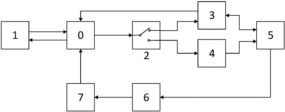
[0032] In this example, a silicon microresonant pressure sensor shell-level test system and its implementation method based on multi-frequency scanning technology are given. Refer to figure 1 . The system is mainly composed of main control chip 0, host computer 1, control switch 2, safety detection module 3, D / A conversion module 4, sensor to be tested 5, interface circuit 6, and A / D conversion module 7. Among them: the main control chip 0 is FPGA; the upper computer 1 is LabVIEW; the main control chip 0 and the upper computer 1 communicate through the UART interface; the sensor 5 to be tested is a silicon micro-resonant pressure sensor; Through the safety detection module 3 or the D / A conversion module 4; the safety detection module 3 mainly carries out the short-circuit test by the transimpedance amplifier, so that the sensor 5 to be tested is initially screened, and simultaneously prevents the sensor 5 to be tested from being damaged by the short circuit of the test circuit...

Embodiment 2

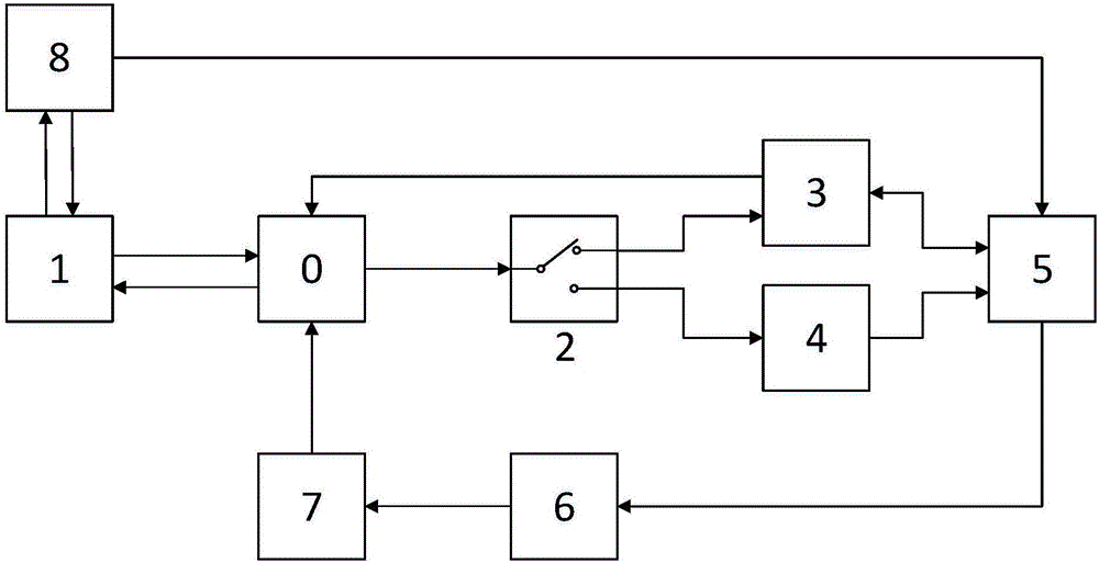
[0046] In this example, a silicon microresonant accelerometer wafer-level testing system based on multi-frequency scanning technology and its implementation method are given. The system can realize automatic testing before sensor packaging. refer to figure 2 , the system is mainly composed of main control chip 0, host computer 1, control switch 2, safety detection module 3, D / A conversion module 4, sensor to be tested 5, interface circuit 6, A / D conversion module 7 and automatic probe station 8 nine parts. Among them, the main control chip 0 is ARM; the host computer 1 is LabVIEW; the main control chip 0 and the host computer 1 communicate through the USB interface; the sensor 5 to be tested is a sensor core on the entire silicon wafer; the main control chip 0 is controlled by The switch 2 gates the safety detection module 3 or the D / A conversion module 4 respectively; the safety detection module 3 mainly performs a short-circuit test by a transimpedance amplifier, so as to ...


PUM


Abstract

The invention discloses a resonant sensor frequency characteristic test system and realization method based on multi-frequency scanning technology, and belongs to the field of a sensor. The test system mainly comprises eight parts: a main control chip 0, an upper computer 1, a control switch 2, a safety detection module 3, a D / A conversion module 4, a sensor to be tested 5, an interface circuit 6 and an A / D conversion module 7. Through the frequency characteristic test method based on multi-frequency scanning, test efficiency is greatly improved under the condition of ensuring test quality; and a hardware circuit of the test system is low in cost, and the system is simple and convenient to use; meanwhile, the system integrates the safety detection module, and can combine with other automatic equipment easily to realize automatic test, thereby further reducing production and research and development cost; and the test data is processed through a digital algorithm, so that the system is high in anti-interference capability, good in system reliability and low in low power consumption.

Description

1. Technical field [0001] The invention relates to the field of sensors, in particular to a frequency characteristic testing system and a realization method of a resonant sensor based on multi-frequency scanning technology. 2. Background technology [0002] The resonant sensor is a type of sensor that uses a resonator to convert the measured physical quantity into a frequency signal. This type of sensor has high precision, good stability, and the output is a quasi-digital signal. The interface is convenient, and it has a very wide range of applications in production and life. . [0003] Testing is an important link in the sensor development process. Efficient testing methods play a vital role in the development and production of resonant sensors, and frequency characteristic testing technology is one of the key technologies for resonant sensor testing. In 2012, Li Xiaoying from Northwestern Polytechnical University proposed a steady-state frequency-sweep silicon resonant pr...

Claims


Application Information

Patent Timeline
IPC IPC(8): G01D18/00
CPCG01D18/00
Inventor 任森程波苑伟政
Owner NORTHWESTERN POLYTECHNICAL UNIV
Learn More