Orifice width adjustable floating body inspection steel gate

An adjustable gate technology, which is applied in water conservancy projects, sea area projects, coastline protection, etc., can solve the problems of fixed width of pontoon-type maintenance stacking beam gates, and can not be used for gate slots with various orifice widths, so as to reduce engineering costs. Effects of construction investment, gate weight reduction and investment saving

Active Publication Date: 2018-02-27
河南省水利勘测设计研究有限公司
View PDF4 Cites 0 Cited by
  • Summary
  • Abstract
  • Description
  • Claims
  • Application Information

AI Technical Summary

Problems solved by technology

[0006] The object of the present invention is to provide a floating body maintenance steel gate with adjustable opening width to solve the problem that the existing floating body maintenance steel gate and buoyant box type maintenance stacking beam gate have fixed widths and cannot be used for gate slots with various opening widths. problems, while meeting the functional requirements of the gate, it saves investment in engineering construction and reduces the difficulty of operation during maintenance operations

Method used


Image

  • Orifice width adjustable floating body inspection steel gate
  • Orifice width adjustable floating body inspection steel gate
  • Orifice width adjustable floating body inspection steel gate

Examples


Embodiment Construction

[0029] The present invention will be described in more detail below through specific embodiments in conjunction with the drawings.

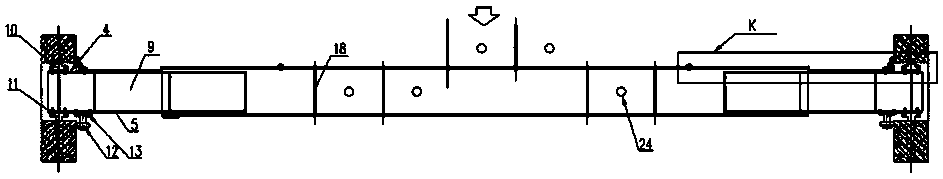
[0030] Such as figure 1 , 2 As shown in 3, the gate leaf of the floating-body inspection steel gate with adjustable orifice width of the present invention is composed of the middle section gate leaf 1 and the left section gate with the same structure and symmetrically overlapped on the left and right ends of the middle section gate leaf 1. The door leaf 2 and the right section of the gate leaf 3 are composed of the sealed box-shaped overlap unit of the right (or left) gate leaf 3 by stacking three layers of sealed box beams spaced up and down. The sealed box beam consists of A three-layer sealed cavity 9 formed by welding the upstream flange plate 4, the downstream flange plate 5, the top web 6 and the bottom web 7, the end and the middle rectangular baffle 8 to produce buoyancy. ; The other end of the gate leaf of the right section (or left section...


PUM


Abstract

The invention discloses a floating body type overhauling steel sluice gate with an adjustable orifice width. A sluice-gate gate leaf of the floating body type overhauling steel sluice gate with the adjustable orifice width consists of an intermediate-section sluice-gate gate leaf, and a left-section sluice-gate gate leaf and a right-section sluice-gate gate leaf which are symmetrically connected to two ends of the intermediate-section sluice-gate gate leaf in a lapping manner; the left-section sluice-gate gate leaf and the right-section sluice-gate gate leaf are the same in structure and are symmetrically arranged; the intermediate-section sluice-gate gate leaf consists of a box-shaped sealing cavity at a middle part and opening adjusting cavities at two ends; sealing box-shaped lapping units of the left-section sluice-gate gate leaf and the right-section sluice-gate gate leaf are connected into the opening adjusting cavities of the intermediate-section sluice-gate gate leaf through sliding rails and sliding ways in an insertion manner; a sluice gate orifice width regulating device is arranged between each of the left-section sluice-gate gate leaf and the right-section sluice-gate gate leaf, and the intermediate-section sluice-gate gate leaf. When the floating body type overhauling steel sluice gate with the adjustable orifice width is designed, stress calculation is carried out according to the maximum width of a sluice gate needing to be overhauled; structural arrangement is carried out according to the maximum width and the minimum width of the sluice gate; the lapping lengths of the left section and the right section on the intermediate section and the number of lapping units are determined according to the height dimension and the thickness dimension of the sluice gate; optimization design is carried out by combining the stress calculation with the structural arrangement, and the stress of the sluice gate is enabled to meet relevant code requirements, and moreover, to meet structural and constructional requirements.

Description

Technical field [0001] The invention relates to an overhaul steel gate for water conservancy projects, in particular to a floating-body overhaul steel gate with an adjustable orifice width. Background technique [0002] The floating gate is a hollow structure, and the structure type is between the ordinary steel gate and the ship. After the gate is in place, the counterweight ballast tank is sealed and the ballast tank is filled with water to achieve the water retaining function. The water in the counterweight ballast tank is pumped After floating on the water surface, the application of this technology in water conservancy projects at home and abroad has become increasingly mature. Floating gates can freely sink and float in the water and are easy to transport. They do not require special opening and closing equipment. They are widely used in inland gates with large openings, navigation gates with navigation requirements, and tide gates in coastal inland rivers. [0003] Some wat...

Claims


Application Information

Patent Timeline
Patent Type & Authority Patents(China)
IPC IPC(8): E02B7/50E02B7/54
CPCE02B7/50E02B7/54
Inventor 马山玉贾少燕高英宋杰陈功军王新平白勇谢冰侯燕张慧萍付海水赵一新李政鹏屈志刚张金辉张玉明胡晓峰赵蕾蕾赵蓓蓓曲晓宁王岩葛均建姚亮亮张波陈雪艳黄哲元孙传军田永军陈秋红韩准严勇
Owner 河南省水利勘测设计研究有限公司
Why Eureka
Try Eureka