Lifting guardrail device used for municipal bridge

A technology of guardrail device and bridge, applied in the direction of bridge, bridge parts, bridge construction, etc.

Active Publication Date: 2016-11-09
TONGXIANG HUIFENG ELECTRICAL APPLIANCE DIE CASTING PLANT
View PDF5 Cites 1 Cited by
  • Summary
  • Abstract
  • Description
  • Claims
  • Application Information

AI Technical Summary

Problems solved by technology

These circuits and other electrical components should often avoid water accumulation and affect normal use.

Method used


Image

  • Lifting guardrail device used for municipal bridge
  • Lifting guardrail device used for municipal bridge
  • Lifting guardrail device used for municipal bridge

Examples


Embodiment Construction

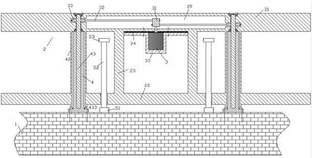
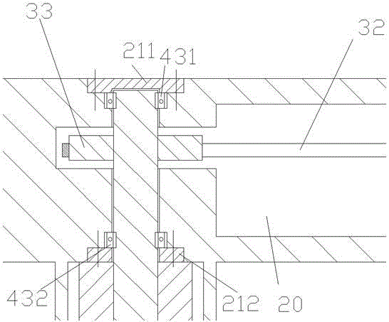
[0009] Combine below Figure 1-3 The present invention will be described in detail.

[0010] According to an embodiment of the present invention, a liftable guardrail device for municipal bridges includes: a bridge base 1 and a plurality of guardrail units 2 installed on the bridge base 1, each guardrail unit 2 including left and right symmetrically fixed to the The two fixed sleeve columns 4 on the bridge base 1, the upper cross beam 21 and the lower cross beam 22 that span and extend beyond the two fixed sleeve columns 4, the upper cross beam 21 and the lower cross beam 22 are both provided There are circuit devices and are fixedly connected by the vertical railing 23; wherein, each of the two fixed sleeve uprights 4 is provided with a screw hole that is threaded with the vertical stud 43. The upper end extends into the upper cross beam 21 and is axially fixedly connected to the upper cross beam 21 through the upper thrust bearing 431 and the lower thrust bearing 432. The vert...


PUM


Abstract

A lifting guardrail device used for a municipal bridge comprises a bridge matrix (1) and a plurality of guardrail units (2) mounted on the bridge matrix (1). Each guardrail unit (2) comprises two fixed sleeve columns (4) fixed on the bridge matrix (1) bilaterally symmetrically, as well as an upper beam (21) and a lower beam (22) which cross and extend over the two fixed sleeve columns (4), wherein each of the upper beam (21) and the lower beam (22) is provided with circuit apparatus, and the upper beam (21) and the lower beam (22) are fixedly connected through vertical railings (23); a screw hole in threaded fit with a vertical stud (43) is formed in each of the two fixed sleeve columns (4), and the upper end of the vertical stud (43) extend into the upper beam (21) and is axially and fixedly connected with the upper beam (21) through an upper thrust bearing (431) and a lower thrust bearing (432).

Description

Technical field [0001] The invention relates to the field of bridges, in particular to a liftable guardrail device for municipal bridges. Background technique [0002] There are often guardrails on both sides of the road surface of the bridge to ensure traffic safety on the road surface of the bridge. In some bridge facilities, in order to provide lighting, aesthetics and safety indicators, the guardrails of the bridge are often equipped with electrical components such as circuits. However, these circuits and other electrical components should often avoid the entry of water and affect normal use. At the same time, the bottom beam of the bridge guardrail may also be equipped with other devices that are easily affected by stagnant water or other road interference factors, such as some sensing devices or beautiful decorative materials. Therefore, in some specific situations, it becomes necessary to adjust the height of the guardrail to prevent the guardrail (especially the bottom ...

Claims


Application Information

Patent Timeline
IPC IPC(8): E01D19/10
CPCE01D19/103
Inventor 吴扬华
Owner TONGXIANG HUIFENG ELECTRICAL APPLIANCE DIE CASTING PLANT
Why Eureka
Try Eureka