Middle filter screen type tentering setting machine

A tenter setting machine and filter screen technology, which is used in heating/cooling fabrics, textiles and papermaking, fabric surface trimming, etc. Ensure the quality of the fabric and avoid the effect of fabric wrinkling

Inactive Publication Date: 2016-11-09
YOANTION IND INC LTD
View PDF6 Cites 0 Cited by
  • Summary
  • Abstract
  • Description
  • Claims
  • Application Information

AI Technical Summary

Problems solved by technology

[0002] See figure 1 As shown, each oven unit A1 of the existing stenter setting machine is provided with a static pressure box A2, the static pressure box A2 is provided with an air outlet pipe A21, and the air nozzle A3 is connected with the air outlet pipe A21. The cloth feeding chain A4 is located below the air nozzle A3, and the cloth 35 is located on the cloth feeding chain A4; the filter screen A6 is located under the cloth 35, and the yarn dust on the cloth 35 is blown to the filter screen A6 by the air nozzle A3, which needs to be manually and periodically Clean filter A6
Its disadvantage is: the static pressure chamber A2 of each oven unit A1 is located on the same side of each oven unit A1, that is, the static pressure chamber A2 on all oven units A1 is all located on the right side of each oven unit A1, so The filter A6 is not located in the middle of the oven unit A1, there is no problem in the production process of the stenter setting machine for general fabrics, but for the stenter setting machine of some fabrics (such as polyester fabrics) that are easily deformed by heat It is easy to cause the cloth to be heated unevenly and cause the surface of the cloth to wrinkle, thus affecting the quality of the processed cloth
The reason is that no matter how the air nozzle is designed, the wind entering the air nozzle A3 cannot be absolutely evenly blown on the fabric. Generally, there is a problem that the right half of the air nozzle A3 has a large air volume, while the left half of the air volume is small.

Method used


Image

  • Middle filter screen type tentering setting machine
  • Middle filter screen type tentering setting machine
  • Middle filter screen type tentering setting machine

Examples


Embodiment Construction

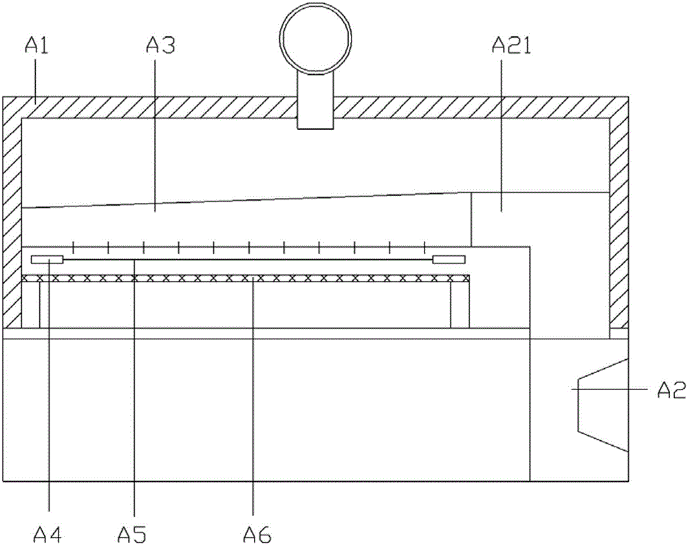
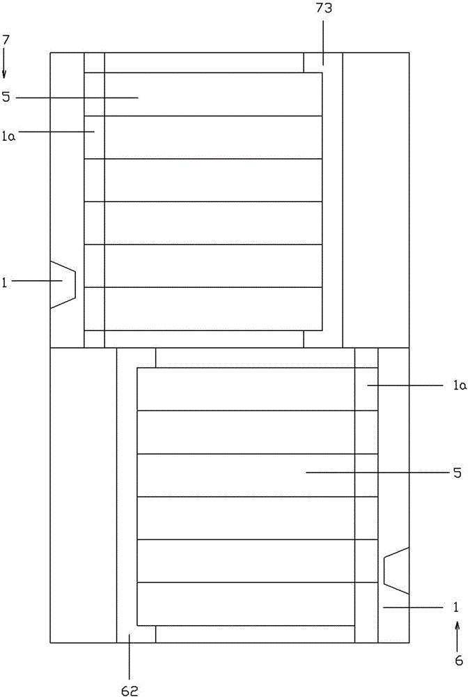
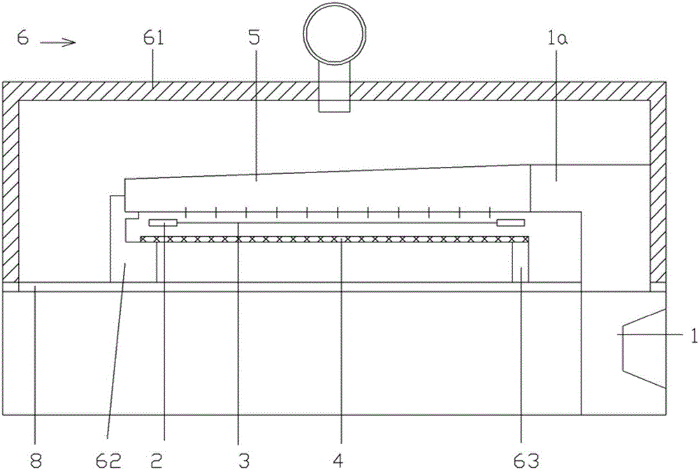
[0015] Example: see Figures 2 to 4 As shown, the intermediate filter type stenter setting machine includes a static pressure box 1, a cloth feeding chain 2, a cloth 3, a filter 4 and an air nozzle 5, and the two sides of the cloth 3 are clamped on the cloth feeding chain 2, and the cloth 3 is located at Below the tuyere 5, the filter screen 4 is located below the fabric 3, the two adjacent oven units of the tenter setting machine are the first oven unit 6 and the second oven unit 7, the structure of the first oven unit 6 is, The bottom of an oven unit casing 61 is a plenum box 1, and the plenum box 1 is positioned at the right side of the first oven unit casing 61. The plenum box 1 has an air outlet pipe 1a, and the air outlet pipe 1a communicates with the tuyere 5. The upper end of static pressure box 1 is fixed with support plate 8, and the first oven unit casing 61 is fixed on the support plate 8, and the first oven left support 62 and the first oven right support 63 are f...


PUM


Abstract

The invention provides a middle filter screen type tentering setting machine. Two adjacent drying oven units of the tentering setting machine are a first drying oven unit and a second drying oven unit; the structure of the first drying oven unit is as follows: a static pressure box is arranged at the lower part of a first drying oven unit oven body, arranged on the right side of the first drying oven unit oven body, and provided with an air discharge pipe, and the air discharge pipe is communicated with an air discharge pipe; a supporting plate is fixed at the upper end of the static pressure box, the first drying oven unit oven body is fixed on the supporting plate, a first drying oven left support and a first drying oven right support are fixed on the supporting plate, the left end of the air discharge pipe and that of a filter screen are fixed on the first drying oven left support, and the right end of the filter screen is fixed on the first drying oven right support. According to the middle filter screen type tentering setting machine, the filter screen is designed at the middle part of the drying oven, so that wind can be blown on cloth crossly and uniformly; therefore, the cloth is prevented from wrinkling, and the quality of processed cloth is ensured.

Description

Technical field: [0001] The invention relates to the technical field of a stenter setting machine, and more specifically relates to a stenter setting machine in which a filter screen is arranged in the middle of an oven. Background technique: [0002] See figure 1 As shown, each oven unit A1 of the existing stenter setting machine is provided with a static pressure box A2, the static pressure box A2 is provided with an air outlet pipe A21, and the air nozzle A3 is connected with the air outlet pipe A21. The cloth feeding chain A4 is located below the air nozzle A3, and the cloth 35 is located on the cloth feeding chain A4; the filter screen A6 is located under the cloth 35, and the yarn dust on the cloth 35 is blown to the filter screen A6 by the air nozzle A3, which needs to be manually and periodically Clean filter A6. Its disadvantage is: the static pressure chamber A2 of each oven unit A1 is located on the same side of each oven unit A1, that is, the static pressure ch...

Claims


Application Information

Patent Timeline
IPC IPC(8): D06C7/02D06C3/02
CPCD06C7/02D06C3/02
Inventor 陈少军丁伯军
Owner YOANTION IND INC LTD
Why Eureka
Try Eureka