Biomass carbonization burner

A burner and biomass technology, applied in the direction of biofuel, special dry distillation, petroleum industry, etc., can solve problems such as pollution and pipeline blockage

Inactive Publication Date: 2016-11-09
雷连净
View PDF7 Cites 3 Cited by
  • Summary
  • Abstract
  • Description
  • Claims
  • Application Information

AI Technical Summary

Problems solved by technology

[0004] The invention provides a biomass charcoal burner. By purifying, purifying and burning the wood gas produced in the carbonization process, it can not only avoid air pollution caused by wood gas discharge, but also completely solve the pollution problem in the production process of mechanism charcoal. The heat energy generated by the combustion of wood gas can be used to heat the carbonization furnace, and at the same time, it solves the technical problem of blockage of various pipelines caused by wood tar

Method used


Image

  • Biomass carbonization burner
  • Biomass carbonization burner
  • Biomass carbonization burner

Examples


Embodiment 1

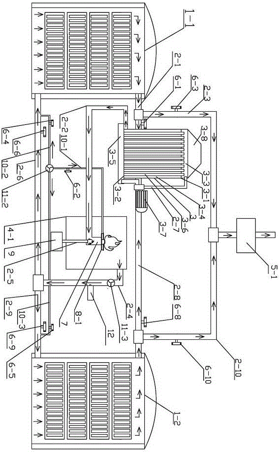
[0037] as attached figure 1 As shown, a biomass charcoal burner includes a symmetrically arranged first carbonization furnace 1-1 and a second carbonization furnace 1-2, and the inner cavity of the purifier 3 passes through the first pipeline 2-1 and the first carbonization furnace 1-1 communicates with the upper part of the inner cavity and communicates with the upper part of the second carbonization furnace inner cavity through the eighth pipeline 2-8, and communicates with the first combustion chamber 4-1 for burning wood gas through the second pipeline 2-2; The upper part of the combustion chamber 4-1 communicates with the lower part of the inner cavity of the second carbonization furnace 1-2 through the fourth pipeline 2-4 and the ninth pipeline 2-9 in sequence, and passes through the fourth pipeline 2-4 and the sixth pipeline 2 in sequence -6 communicates with the lower part of the inner chamber of the first carbonization furnace 1-1; the upper part of the first carboniz...

Embodiment 2

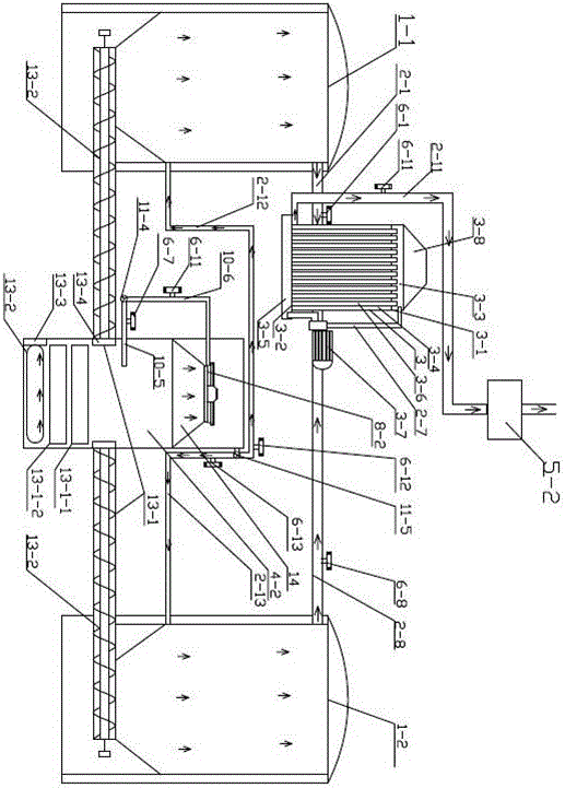
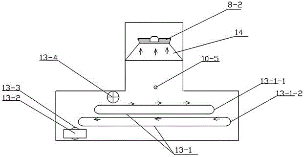
[0053] as attached figure 2 As shown, a biomass charcoal burner includes a symmetrically arranged first carbonization furnace 1-1 and a second carbonization furnace 1-2, and the inner cavity of the purifier 3 passes through the first pipeline 2-1 and the first carbonization furnace The upper part of the inner cavity of 1-1 communicates with the upper part of the inner cavity of the second carbonization furnace 1-2 through the eighth pipeline 2-8, and communicates with the second dust removal device for removing dust and moisture in the exhaust gas through the eleventh pipeline 2-11 5-2; A second combustion chamber 4-2 for burning wood gas is provided between the first carbonization furnace 1-1 and the second carbonization furnace 1-2, and the lower part of the first carbonization furnace 1-1 and the second carbonization furnace 1 The lower part of -2 communicates with the lower part of the second combustion chamber 4-2 through a frequency-modulated feeding device 13-5, and th...


PUM


Abstract

The invention provides a biomass carbonization burner, which comprises a first carbonization furnace and a second carbonization furnace, wherein a purifier is communicated between the first and second carbonization furnaces through a pipeline; an inner cavity of the purifier is communicated with the upper part of an inner cavity of the first carbonization furnace through a first pipeline, is communicated with the upper part of an inner cavity of the second carbonization furnace through an eighth pipeline, and is communicated with a first burning chamber through a second pipeline; the inner upper part of the first burning chamber is communicated with the lower part of the inner cavity of the second carbonization furnace sequentially through a fourth pipeline and a ninth pipeline, and is communicated with the lower part of the inner cavity of the first carbonization furnace sequentially through the fourth pipeline and a sixth pipeline; the inner upper part of the first carbonization furnace is further communicated with a first dust removal device through a third pipeline; the dust removal device is further communicated with the upper part of the inner cavity of the second carbonization furnace. According to the biomass carbonization burner, atmospheric pollution caused by emission of wood gas can be avoided, the carbonization furnaces can also be heated by virtue of heat energy generated by burning of the wood gas, and in addition, the technical problem of blockage of various pipelines by wood tar is solved.

Description

technical field [0001] The invention relates to the technical field of biomass charcoal formation, in particular to a biomass charcoal combustion burner. Background technique [0002] Biomass charring refers to the formation of porous carbon structures from various biomass materials such as wood chips and straws in a high-temperature and oxygen-deficient environment. During the carbonization process of biomass materials, a large amount of high-temperature flue gas such as wood gas will be produced. High-temperature flue gas contains a large amount of biomass heat energy. If it is directly discharged into the air, it will not only pollute the atmosphere, but also cause waste of biomass energy. . [0003] Existing biomass carbonization equipment has the disadvantage of low purification efficiency due to the fact that biomass materials will produce a large amount of wood gas and other high-temperature flue gases during the carbonization process. Therefore, the pollution in the...

Claims


Application Information

Patent Timeline
Patent Type & Authority Applications(China)
IPC IPC(8): C10B53/02C10B57/18C10B57/10
CPCC10B53/02C10B57/10C10B57/18Y02E50/10
Inventor 雷连净
Owner 雷连净
Why Eureka
Try Eureka