
Mold achieving forming through multi-insert dovetail core-pilling mechanism

A core-pulling mechanism and dovetail technology, applied in the field of product forming molds, can solve problems such as the inability to achieve rapid and precise positioning of silicon steel sheet groups, and achieve the effects of simple and compact structure, stable and reliable work, and improved production efficiency

Active Publication Date: 2016-11-09
DALIAN LUANYI PRECISION ENG
View PDF6 Cites 5 Cited by
  • Summary
  • Abstract
  • Description
  • Claims
  • Application Information

AI Technical Summary

Problems solved by technology

In the prior art, when the stator silicon steel sheet group participates in injection molding in the form of an insert, since the outer circumference tolerance of the silicon steel sheet group is generally set to +0.05~0.1mm and the height tolerance is generally set to ±0.1~0.3mm, during the mold design process In order to meet the precision requirements of mold injection molding and ensure the overall dimensional tolerance and shape tolerance of the product, there are high requirements on the mold structure. The traditional method of directly installing the insert in the mold cavity cannot realize the rapid and precise positioning of the silicon steel sheet group.

Method used


Image

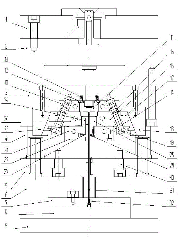
  • Mold achieving forming through multi-insert dovetail core-pilling mechanism
  • Mold achieving forming through multi-insert dovetail core-pilling mechanism
  • Mold achieving forming through multi-insert dovetail core-pilling mechanism

Examples


Embodiment Construction

[0017] Specific embodiments of the invention will be described in detail below in conjunction with technical text and accompanying drawings.

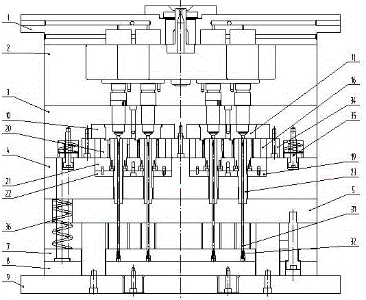
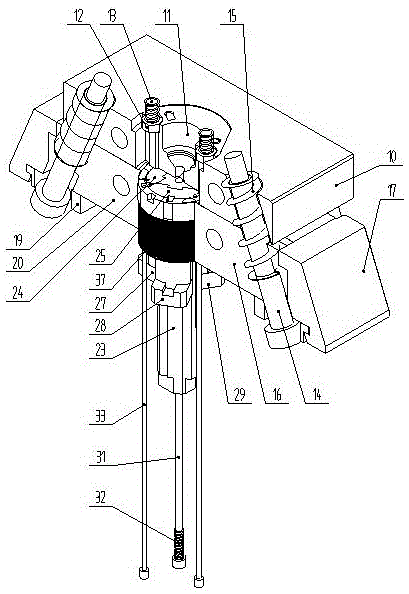
[0018] When assembling the mold, the fixed mold core 12 is installed in the mold cavity processed by the fixed mold insert 11 and is limited by the hanger, and the fixed mold insert 11 is installed in the mold cavity processed by the fixed mold insert 10 by the hanger. position, the spring A13 is installed in the counterbore hole processed by the fixed template 3, the fixed mold insert 10 is installed in the cavity processed by the fixed template 3, and the bolts pass through the fixed template 3 to lock and fix it with the fixed template 3. The positioning plate 34 is installed in the mold cavity processed by the fixed template 3, and the bolt passes through the fixed template 3 to lock and fix it with the fixed template 3, and the two slider seats 17 are assembled with the slider A16 and the slider B20 respectively, and the bolts Thro...


PUM


Abstract

The invention provides a mold achieving forming through a multi-insert dovetail core-pilling mechanism and belongs to the field of molds for thermoplastic plastics. The mold achieving forming through the multi-insert dovetail core-pilling mechanism solves the problems existing in the locating process of a silicon steel sheet group and in the molding process through the multi-insert dovetail core-pilling mechanism. A movable mold insert A24, a movable mold insert B25, a movable mold insert C26 and a movable mold center insert 23 slide through guiding of dovetail grooves to achieve centered motion, and space is reserved for initial assembly of the silicon steel sheet group 37. A sliding block A16 and a sliding block B20 achieve horizontal movement under the cooperative action of a shouldered bolt A14, a spring B15 and a wedge 18, and therefore the silicon steel sheet group 37 is finally located. A spring A13 acts on a fixed mold core 12 so that mold assembly can be adjusted according to the height of the silicon steel sheet group 37 through the fixed mold core 12; and in this way, the assembly difficulty is overcome, the mold precision is guaranteed, and the silicon steel sheet group 37 is protected against damage caused by press. The structure is stable and reliable in work and capable of rapidly and accurately locating the silicon steel sheet group 37 and enables a product to be rapidly disengaged from the mold and meet technical and use requirements, the space of the mold is effectively utilized, the structure is simple and compact, and the production efficiency is improved.

Description

technical field [0001] The invention belongs to the field of molding molds for thermoplastic plastics, and relates to molds formed by a multi-insert dovetail core-pulling mechanism, and are mainly used in molding molds for products requiring pre-positioned silicon steel sheet groups. Background technique [0002] The motor stator is an important part of motors such as generators and starters, and the stator is an important part of the motor. The stator is composed of three parts: stator core, stator winding and frame. The silicon steel sheets that make up the stator often require injection molding for secondary processing. In the prior art, when the stator silicon steel sheet group participates in injection molding in the form of an insert, since the outer circumference tolerance of the silicon steel sheet group is generally set to +0.05~0.1mm and the height tolerance is generally set to ±0.1~0.3mm, during the mold design process In order to meet the precision requirements...

Claims


Application Information

Patent Timeline
Patent Type & Authority Applications(China)
IPC IPC(8): B29C45/33B29C45/40
CPCB29C45/33B29C45/332B29C45/40
Inventor 张嘉王强赵刚
Owner DALIAN LUANYI PRECISION ENG
Learn More