Wire feeding mechanism

A technology of wire feeding mechanism and wire feeding gear, which is applied to arc welding equipment, manufacturing tools, welding equipment, etc., can solve problems such as inability to ensure success rate, low work efficiency, troublesome operation, etc., and achieve enhanced work continuity and improved Improvement of welding quality and productivity

Inactive Publication Date: 2016-11-09
陈铭鸿
View PDF4 Cites 0 Cited by
  • Summary
  • Abstract
  • Description
  • Claims
  • Application Information

AI Technical Summary

Problems solved by technology

[0002] The welding machine is equipped with a wire feeding mechanism to realize automatic production, but the fuselage of the wire feeding mechanism in the prior art is integrally formed, and manual wire threading before welding cannot observe the wire threading situation in real time. It is easy to bend at the time, and needs to be repeatedly interspersed, which cannot ensure a 100% success rate, and the operation is cumbersome and complicated; the existing wire feeding mechanism only has a wire feeding gear inside, and the welding wire is likely to shift when the welding machine is working , thereby affecting the quality of welding; in addition, the existing wire feeding mechanism can only coordinate with one welding machine, and its work efficiency is low and the cost is high; in addition, the existing wire feeding machines all use ordinary motors, which cannot be transported at fixed lengths Welding wire, which requires manual control, is not easy to operate and has low efficiency

Method used


Image

  • Wire feeding mechanism
  • Wire feeding mechanism
  • Wire feeding mechanism

Examples


Embodiment Construction

[0018] The present invention will be described in further detail below in conjunction with the accompanying drawings.

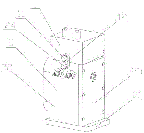
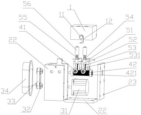
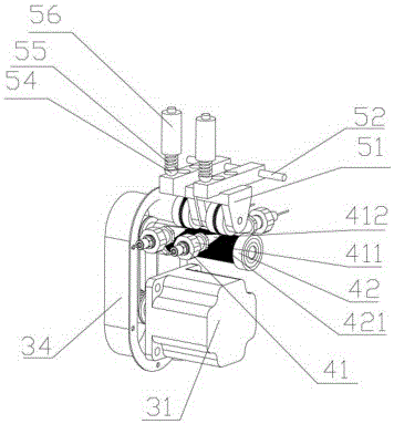
[0019] 1 to 3 schematically show a wire feeding mechanism according to the present invention.

[0020] According to one aspect of the present invention, a wire feeding mechanism is provided, including an upper cover 1, a body 2, a stepping drive mechanism, a wire feeding mechanism and a positioning mechanism; wherein the body 2 includes an interconnected base 21, a "concave" shape The frame 22 and the fixing plate 23 adopt a split structure, which is more convenient and quick in assembly, disassembly and maintenance.

[0021] Stepping drive mechanism comprises stepping motor 31, delivery wheel 32, transmission belt 33 and protection frame 34, and stepping motor 31 is installed in the lower end of frame 22, and the rotor of stepping motor 31 passes through frame 22 and connects with delivery wheel 32 connection, the protective frame 34 is fixed on one side of...


PUM


Abstract

The invention discloses a wire feeding mechanism which comprises an upper cover, a machine body, a step driving mechanism, at least two wire feeding mechanisms and a positioning mechanism, wherein the step driving mechanism is mounted in the machine body through a bolt, and fixed-length output of a welding wire is realized through the arrangement of the step driving mechanism; the upper cover is movably connected with the machine body in an opening-closing way, and is provided with an opening-closing mechanism which can realize flexible opening and closing of the upper cover to facilitate insertion of the welding wire at a wire feeding state; each wire feeding mechanism comprises two wire guiders fixed on the machine body and a wire feeding gear, the two wire guiders are provided with through holes that are located on the same horizontal axis after the two wire guiders are fixed, and the wire feeding gear is arranged between the two wire guiders and connected with the step driving mechanism; and the positioning mechanism is mounted in the upper cover, is located above the wire feeding gears, and can be closely combined with the wire feeding gears during operation. According to the wire feeding mechanism provided by the invention, the upper cover can be opened to facilitate insertion of the welding wire, the working continuity is high, fixed-length output of the welding wire is realized, the production efficiency is improved, and waste is avoided.

Description

technical field [0001] The invention relates to the field of welding equipment, in particular to a wire feeding mechanism of a welding machine. Background technique [0002] The welding machine is equipped with a wire feeding mechanism to realize automatic production, but the fuselage of the wire feeding mechanism in the prior art is integrally formed, and manual wire threading before welding cannot observe the wire threading situation in real time. It is easy to bend at the time, and needs to be repeatedly interspersed, which cannot ensure a 100% success rate, and the operation is cumbersome and complicated; the existing wire feeding mechanism only has a wire feeding gear inside, and the welding wire is likely to shift when the welding machine is working , thereby affecting the quality of welding; in addition, the existing wire feeding mechanism can only coordinate with one welding machine, and its work efficiency is low and the cost is high; in addition, the existing wire ...

Claims


Application Information

Patent Timeline
IPC IPC(8): B23K9/133
CPCB23K9/133
Inventor 陈铭鸿
Owner 陈铭鸿
Why Eureka
Try Eureka