Powder coating equipment and coating technology

A coating process and equipment installation technology, which is applied to liquid spray devices, devices that apply liquid to surfaces, coatings, etc., to achieve the effects of long service life, increased powder charge, and reduced friction

Active Publication Date: 2016-11-09
WEIFANG EAST PIPE IND TECHNICAL CO LTD
View PDF6 Cites 3 Cited by
  • Summary
  • Abstract
  • Description
  • Claims
  • Application Information

AI Technical Summary

Problems solved by technology

[0004] The technical problem to be solved by the present invention is to provide a kind of powder coating equipment and coating process in view of the deficiencies in the prior art, wherein the equipment uses a high-pressure powder chamber as a powder supply source, which improves the powder coating efficiency. The floating rate is 15-20%, and the centrifugal effect generated by the rotation of the blades is used to solve the uniformity problem in the powder fluidization process

Method used


Image

  • Powder coating equipment and coating technology
  • Powder coating equipment and coating technology

Examples


Embodiment Construction

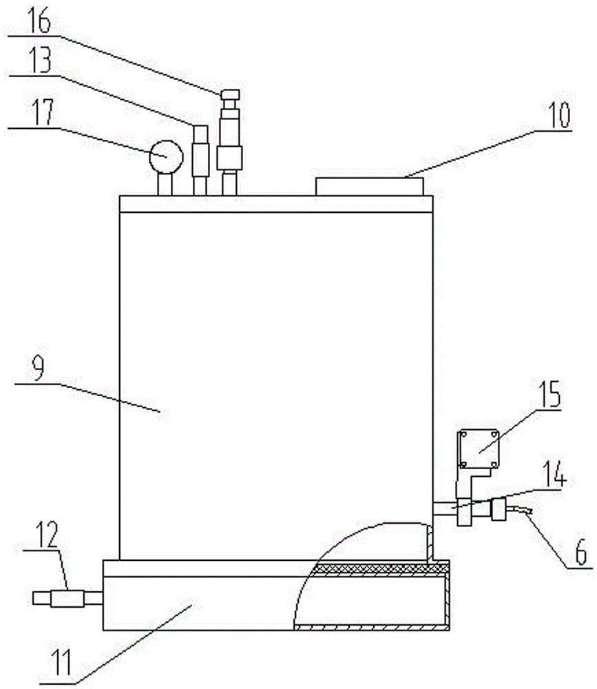
[0028] For the convenience of description, the powder coating equipment of the invention will be described in detail below in conjunction with the accompanying drawings.

[0029] Such as Figure 1 to Figure 2 As shown in , a powder coating equipment includes a spray gun part, and the spray gun part includes a conical powder outlet 1, and an impeller 2 is installed in the powder outlet 1, and the impeller 2 is connected with the powder There is a powder circulation gap 3 between the outlets 1; the mixing chamber 4 on the upper part of the impeller 2, the mixing chamber 4 is installed on the powder outlet 1, and the mixing chamber 4 is located above the back of the impeller 2 , and arranged in a ring shape; the mixing chamber 4 includes a chamber wall, the chamber wall is provided with a passage 5 communicating with the mixing chamber 4, and the passage 5 is connected with a powder supply pipeline 6; The impeller 2 is also connected with a motor 7 or a motor that provides power...


PUM


Abstract

The invention provides a piece of powder coating equipment which comprises a spraying gun part, wherein the spraying gun part comprises a powder outlet which is disposed in a conical manner; an impeller is installed in the powder outlet; a powder circulation gap is disposed between the impeller and the powder outlet; a mixing chamber is disposed on the upper part of the impeller and installed at the powder outlet; the mixing chamber is located above the back face of the impeller and disposed in an annular manner; and the mixing chamber comprises a chamber wall, a channel communicating with the mixing chamber is formed in the chamber wall, and a power supply pipeline is connected to the channel. According to the invention, the high-voltage powder chamber is used as a powder supply source; a powder floating rate is increased by 15%-20%; and centrifugal effects generated from impeller rotation are used to solve the uniformity problem existing in powder fluidization.

Description

technical field [0001] The invention relates to the technical field of mechanical equipment, in particular to a spraying equipment, in particular to a powder coating equipment and a coating process. Background technique [0002] At present, the powder coating equipment adopts the Venturi powder pump conveying and spraying method, and the compressed air drives the powder to achieve high-speed conveying to complete the spraying. The powder jet obtained in this way presents the characteristics of high speed, high air content and low powder density. [0003] The high-speed jet leads to serious rebound of powder particles, and the powder feeding rate is low; the low powder density makes it difficult to improve the spraying efficiency, especially in the case of long-distance spraying, and the high air content creates great pressure on the dust collection and recovery system, resulting in The dust removal system has high power and large volume, and powder spillage is unavoidable, w...

Claims


Application Information

Patent Timeline
Patent Type & Authority Applications(China)
IPC IPC(8): B05B7/14B05B3/08B05B1/06B05D1/12
CPCB05B1/06B05B3/087B05B7/1436B05D1/12
Inventor 桑洪涛于志松陈丽芳赵明印邓建新张向东
Owner WEIFANG EAST PIPE IND TECHNICAL CO LTD
Why Eureka
Try Eureka