
Transplanter end executor

A technology of end effector and actuator, which is applied in the direction of transplanting machinery, planting methods, applications, etc., can solve the problem of complex four-finger structure, comprehensive performance affecting the working efficiency of transplanting machine and the success rate of transplanting, and the inability to plant different seedlings Flexibility and other issues

Inactive Publication Date: 2016-11-09
安徽富牧通生物科技有限公司
View PDF5 Cites 4 Cited by
  • Summary
  • Abstract
  • Description
  • Claims
  • Application Information

AI Technical Summary

Problems solved by technology

[0002] Due to the adjustment of my country's rural industrial structure and the increase in the proportion of farmers going out for employment, labor costs have been significantly higher than mechanized operations. Therefore, it is imperative to develop automated and mechanized transplanting and improve its transplanting efficiency. In the design of the device, the clamping angle of the end is generally not adjustable, and it cannot be flexibly adjusted for different seedling plants, resulting in damage to the seedlings. In addition, the design mostly adopts two-finger and four-finger designs, and the two-finger clamping stability is poor. The four-finger structure is relatively complicated. Aiming at the above problems, a three-finger transplanting end effector with adjustable clamping angle is designed. The transplanting end effector is an important component of the automatic transplanting machine. Its comprehensive performance is Good or bad directly affects the overall working efficiency of the transplanting machine and the success rate of transplanting

Method used


Image

  • Transplanter end executor
  • Transplanter end executor

Examples


Embodiment Construction

[0014] The following will clearly and completely describe the technical solutions in the embodiments of the present invention with reference to the accompanying drawings in the embodiments of the present invention. Obviously, the described embodiments are only some, not all, embodiments of the present invention.

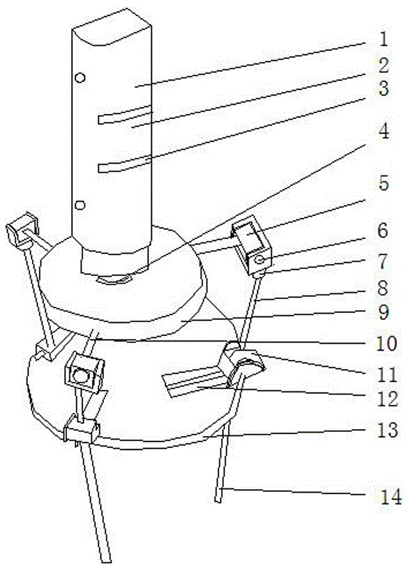
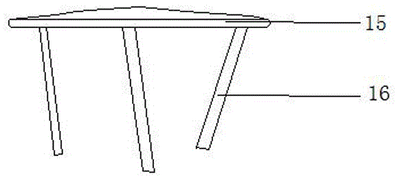
[0015] refer to Figure 1-2 , an end effector for a transplanting machine, comprising an actuator main body 2, a moving plate 9 and a transplanting fixed pointer plate 15, an air tank 1 is installed directly above the actuator main body 2, and an air tank lock is installed in the middle of the actuator main body 2 Tighten the nut 4, a moving plate 9 is installed in the middle of the actuator body 2, a slider 5 is installed around the actuator body 2, an indexing device 11 is installed under the actuator body 2, and a fixed disk 13 is installed directly below the actuator body 2, A fixed plate connecting rod 8 is installed in the middle of the actuator main body 2, an...


PUM


Abstract

The invention discloses a transplanter end executor which comprises an executor body, a movable disc and a transplanting fixing pointer disc. An air tank is mounted right above the executor body, an air tank locking nut is arranged in the middle of the executor body, the movable disc is mounted in the middle of the executor body, sliders are arranged around the executor body, a scaling device is mounted below the executor body, a fixed disc is mounted right below the executor body, a fixed disc connecting rod is mounted in the middle of the executor body, a pin is mounted on the surface of each slider, and movable transplanting pointers are arranged around the lower surface of the transplanting fixing pointer disc. A groove is formed in the air tank, so that surface friction force of the air tank is increased, and air circulation is improved; the air tank locking nut is mounted below the air tank to fix the same, so that the circumstance that the air tank falls down in the process of construction due to serious vibration is prevented; the movable disc is mounted below the executor body, so that convenience is brought to pointer moving.

Description

technical field [0001] The invention relates to the technical field of agricultural production, in particular to an end effector of a transplanting machine. Background technique [0002] Due to the adjustment of my country's rural industrial structure and the increase in the proportion of farmers going out for employment, labor costs have been significantly higher than mechanized operations. Therefore, it is imperative to develop automated and mechanized transplanting and improve its transplanting efficiency. In the design of the device, the clamping angle of the end is generally not adjustable, and it cannot be flexibly adjusted for different seedling plants, resulting in damage to the seedlings. In addition, the design mostly adopts two-finger and four-finger designs, and the two-finger clamping stability is poor. The four-finger structure is relatively complicated. Aiming at the above problems, a three-finger transplanting end effector with adjustable clamping angle is desi...

Claims


Application Information

Patent Timeline
Patent Type & Authority Applications(China)
IPC IPC(8): A01C11/02
CPCA01C11/02
Inventor 陈香全
Owner 安徽富牧通生物科技有限公司
Learn More