
display device

A technology for display devices and display panels, which is applied in the directions of instruments, calculations, and electrical digital data processing, etc., and can solve problems such as falling off of the protection board and falling of the protection board, and achieve the effect of suppressing the drop and preventing the deterioration of the appearance design

Active Publication Date: 2019-07-05
MITSUBISHI ELECTRIC CORP
View PDF7 Cites 0 Cited by
  • Summary
  • Abstract
  • Description
  • Claims
  • Application Information

AI Technical Summary

Problems solved by technology

[0006] As shown in Patent Document 1, in the structure in which the intermediate frame for fixing the protective plate is fixed to the rear frame through the vibration-proof body, when a force exceeding the impact that the adhesive material for fixing the protective plate can withstand is applied In this case, there is a problem that the protective plate comes off from the bonding material or the intermediate frame, and the protective plate falls

Method used


Image

  • display device
  • display device
  • display device

Examples


Embodiment approach 1

[0029]

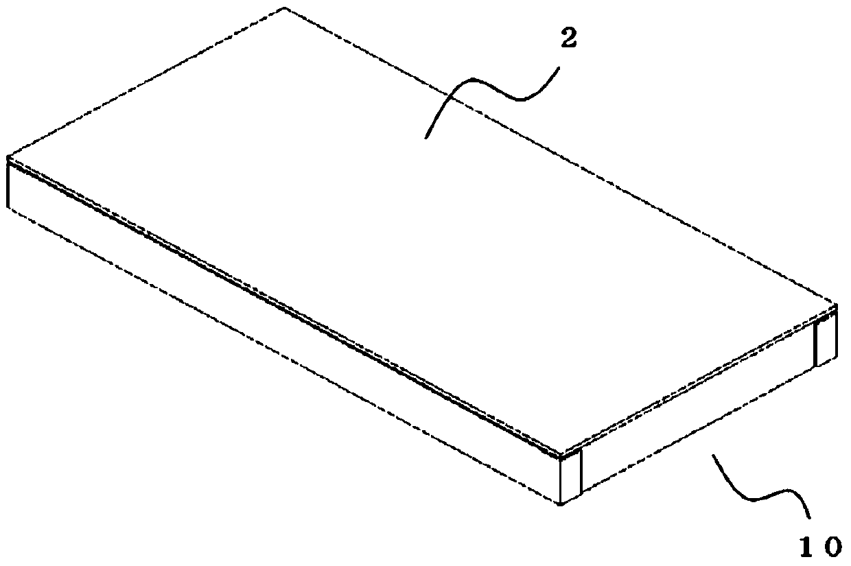
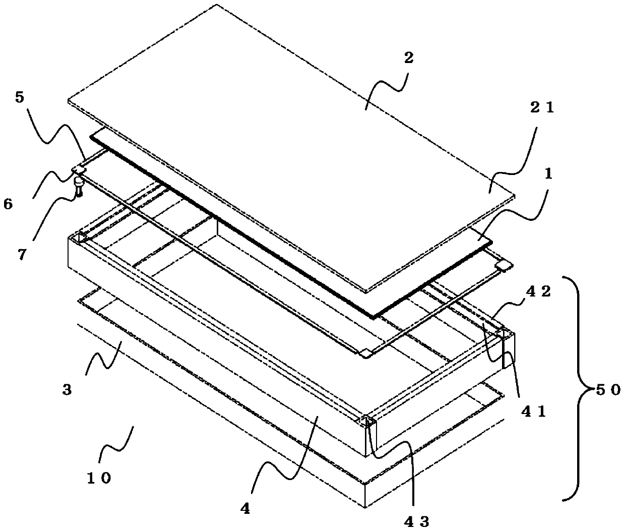
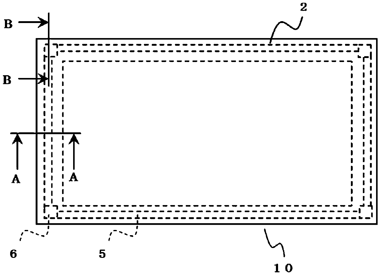
[0030] figure 1 is a perspective view of a display device in an embodiment of the present invention, figure 2 yes figure 1 The exploded oblique view of the display device, image 3 yes figure 1 front view. In addition, in this invention, the same code|symbol is attached|subjected to the element which has the same or equivalent function.

[0031] Such as Figure 1 to Figure 3 As shown, the display device 10 of the present invention has a display panel 1 such as a liquid crystal display panel and a light source device 50. The display panel 1 is used to display images. The light source device 50 illuminates the display panel 1. In front of the display panel 1 On the surface, a protective plate 2 made of, for example, glass is arranged. The light source device 50 is configured by disposing optical components (not shown) such as a light source, a light guide plate, and other components (reflectors, optical sheets) on the rear frame 3 having an opening, the light s...

Embodiment approach 2

[0056] Figure 8 , Figure 9 It is a sectional view of the display device in Embodiment 2. FIG. In Embodiment 1, the fixing member 7 provided on the intermediate frame 4 is configured to have a drop-prevention structure for fixing the protection plate 2, but in Embodiment 2, as Figure 8 As shown, no fixing member is arranged, and a support portion 48 is provided in a region of the intermediate frame 4 corresponding to the second adhesive member 6 , and a hole 47 is formed corresponding to the support portion 48 . In addition, descriptions of the same configurations and effects as those in Embodiment 1 are omitted.

[0057] Such as Figure 8 As shown, a hole 47 is provided corresponding to the supporting portion 48 of the intermediate frame 4 corresponding to the second bonding member 6 . Such as Figure 9 As shown, when an impact is applied to the protective plate 2, the intermediate frame 4 deforms, thereby absorbing and relaxing the impact applied to the protective pla...


PUM


Abstract

A display device includes: a display panel; a light source unit, which irradiates the display panel; a frame, which supports the display panel and the light source unit; and a protective plate, which is disposed on a front surface of the display panel, wherein the protective plate provided with: an adhesive member disposed in a peripheral area of the frame and; a fixing member that is supported by the adhesive member at a position corresponding to the adhesive member disposed in the peripheral area of the frame and is fixed to a fitting portion formed in the frame to be fixed to the frame, and wherein the fixing member includes a fall-prevention structure portion to suppress the protective plate from falling from the frame.

Description

technical field [0001] The present invention relates to a display device including a protective plate for protecting a display surface. Background technique [0002] In general, in display devices used in electrical equipment of automobiles and various other devices, a protective plate may be disposed on the frontmost surface (display surface) of the display device. The protection plate has a structure that is pasted on the middle frame of the light source device, or on a frame that is installed to illuminate the display device, and the frame holds the display device. [0003] In a display device mounted on an automobile (vehicle) electrical equipment, etc., if the display device and its front surface (display surface) have a protective plate, if a very large impact is applied to the display device, the protective plate may be removed from the display. The device fell. In order to securely hold the protective plate, it is necessary to make the bonding area a wide area, and...

Claims


Application Information

Patent Timeline
Patent Type & Authority Patents(China)
IPC IPC(8): G02F1/1333
CPCG02F1/1333G02F1/133308G02F2202/28G06F1/1601G06F2200/1612G02F1/133331
Inventor 国生崇文
Owner MITSUBISHI ELECTRIC CORP
Learn More