Treatment cassette and image forming apparatus

A technology for processing cartridges and equipment, which is applied in the fields of electrography, optics, instruments, etc., to achieve the effects of suppressing toner deposition and dropping

Active Publication Date: 2010-06-09
CANON KK
View PDF6 Cites 0 Cited by
  • Summary
  • Abstract
  • Description
  • Claims
  • Application Information

AI Technical Summary

Problems solved by technology

This is because of the following reasons

Method used


Image

  • Treatment cassette and image forming apparatus
  • Treatment cassette and image forming apparatus
  • Treatment cassette and image forming apparatus

Examples


Embodiment Construction

[0065] Hereinafter, preferred embodiments of the present invention will be exemplarily described in detail with reference to the accompanying drawings. Here, the dimensions, materials, and shapes of components described in the embodiments and their relative placement should vary depending on the configuration of the device to which the present invention is applied and various types of conditions, and the scope of the present invention is not intended to be limited to the following embodiments.

[0066] Image forming equipment:

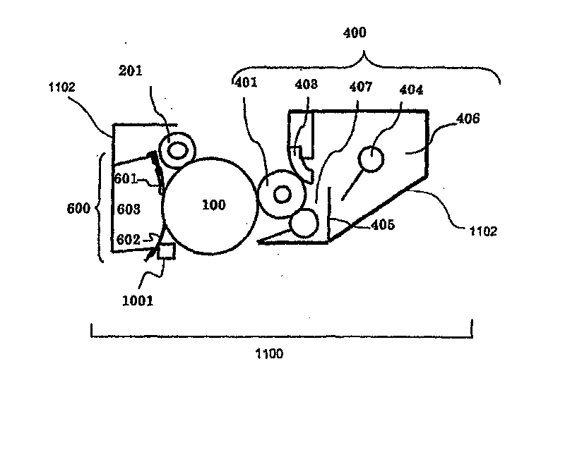
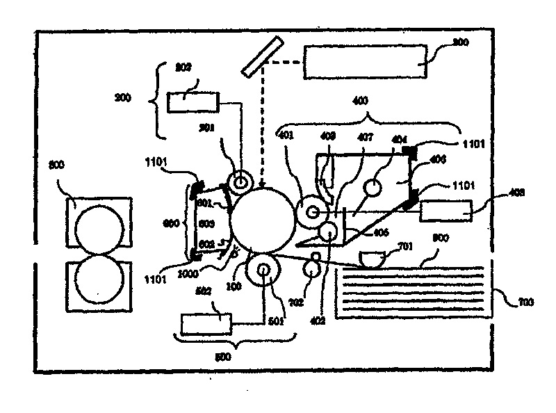
[0067] figure 1 is a schematic explanatory diagram of a process cartridge according to an embodiment of the present invention. figure 2 is an explanatory diagram of an electrophotographic image forming apparatus employing the above-described process cartridge.

[0068] In this example, if figure 1 As illustrated, the process cartridge 1100 is mounted to a mounting portion 1101 provided in the main body of the image forming apparatus (see figure...


PUM


Abstract

An image forming apparatus in which toner left on a seal sheet after transfer is deposited under a high-temperature, high-humidity environment, and falling off of deposited toner is suppressed. In theimage forming apparatus comprising a photosensitive drum (100), a cleaning blade (601) for removing toner, a section (603) for containing toner removed by the cleaning blade (601), and a seal sheet (602) for preventing leakage of toner, in order to effect neutralization on the upstream side, in the moving direction of the drum (100), of the seal sheet (602), the difference in work function between the seal sheet (602) and the photosensitive drum (100) is set at 0.25 eV or above.

Description

technical field [0001] The present invention relates to a process cartridge and an image forming apparatus including a cleaning member for removing developer remaining on an electrophotographic photosensitive member after a developer image is transferred from the electrophotographic photosensitive member to a recording medium. Background technique [0002] An electrophotographic image forming apparatus forms a latent image on an electrophotographic photosensitive member, then develops the latent image into a visible image using a developer (hereinafter referred to as "toner"), and transfers the toner image to Print to the recording medium to complete the image formation. In such an electrophotographic image forming apparatus, a cleaning device removes foreign matter such as transfer residual toner from an electrophotographic photosensitive member after transfer is completed in preparation for reuse of the electrophotographic photosensitive member. [0003] Figure 9 The pho...

Claims


Application Information

Patent Timeline
IPC IPC(8): G03G21/10G03G5/047
CPCG03G21/1832
Inventor 河田健太郎
Owner CANON KK
Why Eureka
Try Eureka