Indoor unit for air-conditioning apparatus

A technology for indoor units and air conditioners, applied in the field of indoor units, can solve problems such as falling and being unable to support the self-weight of blades, and achieve the effect of suppressing falling and suppressing the falling of blades

Active Publication Date: 2015-02-11
MITSUBISHI ELECTRIC CORP
View PDF8 Cites 0 Cited by
  • Summary
  • Abstract
  • Description
  • Claims
  • Application Information

AI Technical Summary

Problems solved by technology

[0004] However, in the bathroom heating equipment described in Patent Document 1, there is a problem that the rotation shaft of the blade receiving the rotational force from the stepping motor (motor) of the air direction adjustment shutter (blade) breaks before the other rotation shaft of the blade. In some cases, the rotating shaft of the other side of the blade cannot support the self-weight of the blade in the direction of falling, so it falls into the indoor space.

Method used


Image

  • Indoor unit for air-conditioning apparatus
  • Indoor unit for air-conditioning apparatus
  • Indoor unit for air-conditioning apparatus

Examples


Embodiment Construction

[0019] Hereinafter, an air conditioner according to an embodiment of the present invention will be described by taking an indoor unit of a four-way box-shaped air conditioner as an example. In addition, this invention is not limited to embodiment shown below. In addition, in the following description, words indicating positions (for example, "upper" and "lower") are appropriately used for easy understanding, but these words are for explanation and do not limit the present invention.

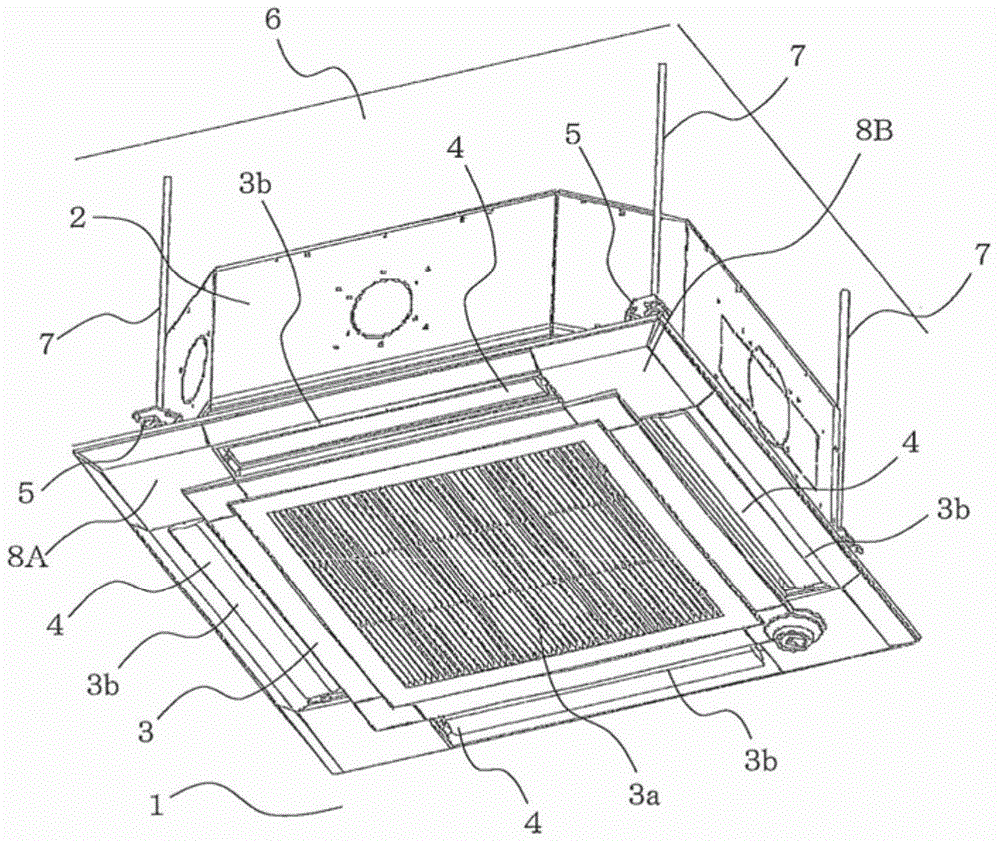
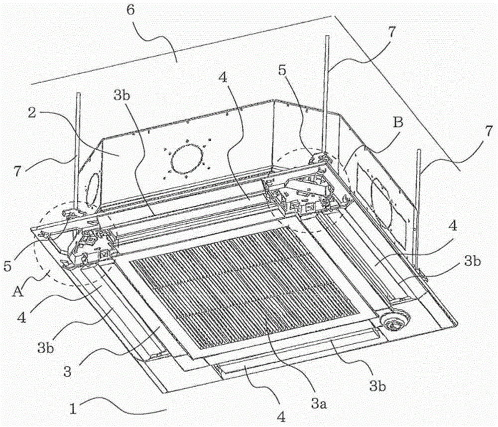
[0020] figure 1 It is a perspective view showing the installation state of the indoor unit 100 of the air conditioner according to the embodiment. figure 2 It is a perspective view showing the indoor unit 100 of the air conditioner according to the embodiment, and shows a state where the corner covers 8A and 8B of the decorative panel are removed.

[0021] Such as figure 1 As shown, an indoor unit 100 of an air conditioner includes a housing 2 in an indoor space 1 . There are 4 suspension ...


PUM


Abstract

An indoor unit 100 of an air-conditioning apparatus includes vanes 4, vane shafts 4a and 4b, which are disposed at the ends of the vanes 4, vane bearings 11 and 12, which hold the vane shafts 4a and 4b, and motors 9, each of which is mounted on a corresponding one of the vane shafts 4a and each of which causes a corresponding one of the vanes 4 to rotate. Each of the vane shafts 4b is provided with a rib 4c, and each of the vane bearings 12, which hold the corresponding vane shafts 4b, is provided with a hook portion 12c. When one of the vane shafts 4b moves by a reference movement amount in a direction toward the corresponding vane shaft 4a, the corresponding rib 4c and the corresponding hook portion 12c engage with each other, so that movement of the vane shaft 4b is restricted.

Description

technical field [0001] The present invention relates to an indoor unit of an air conditioner. Background technique [0002] Conventionally, there is a bathroom heating device that includes: a frame member having a bearing portion and an air outlet formed therein; an air outlet unit having a motor storage box connected to the frame member; and a wind direction adjustment louver. , which has rotation shafts on the left and right sides, and is rotatably supported by the frame member; and a stepping motor for driving the blind, which is stored in a motor storage box (for example, refer to Patent Document 1). In the bathroom heating device described in Patent Document 1, the rotation shaft of the wind direction adjustment louver is connected to the drive shaft of the stepping motor. [0003] Patent Document 1: Japanese Unexamined Patent Publication No. 2003-14286 (page 3, Figure 5 ) [0004] However, in the bathroom heating equipment described in Patent Document 1, there is a ...

Claims


Application Information

Patent Timeline
Patent Type & Authority Applications(China)
IPC IPC(8): F24F1/00F24F13/10
CPCF24F13/1486F24F13/1413F24F2001/0037F24F13/08F24F1/0014F24F1/0011F24F1/00F24F1/0047
Inventor 松永尚也丸山雅晃
Owner MITSUBISHI ELECTRIC CORP
Why Eureka
Try Eureka