
Rigid tension pendulum for bridge

A tension pendulum, rigid technology, applied in the direction of bridges, bridge construction, bridge parts, etc., can solve the problem of bridge negative reaction force, etc., to achieve the effect of convenient maintenance, clear force, and easy installation

Inactive Publication Date: 2016-11-02
CHINA RAILWAY ERYUAN ENG GRP CO LTD
View PDF6 Cites 1 Cited by
  • Summary
  • Abstract
  • Description
  • Claims
  • Application Information

AI Technical Summary

Problems solved by technology

[0005] The technical problem to be solved by the present invention is to provide a bridge rigid tension pendulum, which can effectively solve the problem of negative reaction force of the bridge, and can adapt to the change of the longitudinal bridge direction displacement of the beam end, and does not need to be replaced within the design life of the bridge.

Method used


Image

  • Rigid tension pendulum for bridge
  • Rigid tension pendulum for bridge

Examples


Embodiment Construction

[0013] The present invention will be further described below in conjunction with the accompanying drawings and embodiments.

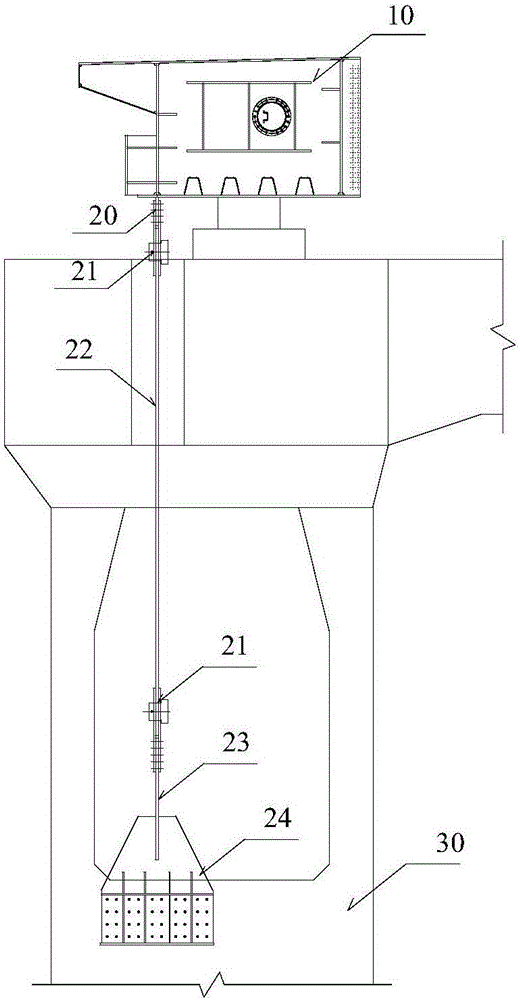
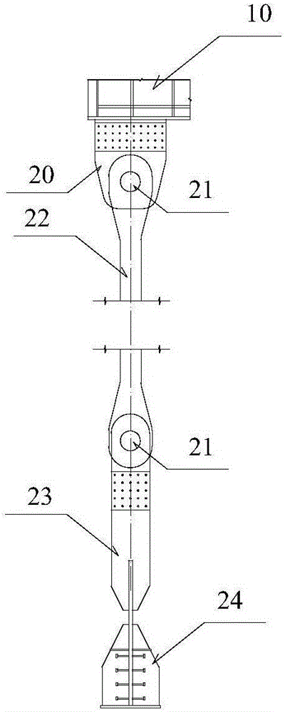
[0014] refer to figure 1 and figure 2 , the bridge rigid tension pendulum of the present invention comprises the pull-up plate 20 fixedly arranged on the longitudinal end of the beam body 10 and the anchor device 24 fixedly arranged on the bridge abutment 30, and the steel eye rod 22 passing through the top hat and the pier column . The upper end and the lower end of the steel eye bar 22 are respectively hinged with the upper pull plate 20 and the lower pull plate 23 through the pin shaft 21, and the bottom of the steel eye bar 22 is fixedly connected with the anchoring device 24.

[0015] refer to figure 1 , the pull-up plate 21 is connected to the beam body 10 by welding, and the pull-down plate 24 is connected to the bridge abutment 30 through the anchoring device 25 . When an upward reaction force appears at the beam end, the rigid tension pend...


PUM


Abstract

The invention relates to a rigid tension pendulum for a bridge. The objective of the invention is to effectively solve the problem of negative reaction of the bridge. The rigid tension pendulum is adaptive to the longitudinal displacement of a beam end and is not required to be replaced in the design life of the bridge. The rigid tension pendulum comprises an upper pull plate which is fixedly arranged on the longitudinal end portion of a beam body, an anchoring device which is fixedly arranged on a bridge pier, and a steel-eye rod which passes through a top cap and a pier column; the upper end and lower end of the steel-eye rod are respectively connected with the upper pull plate and a lower pull plate respectively through hinges; and the lower part of the steel eye rod is fixedly connected with the anchoring device.

Description

technical field [0001] The invention relates to bridges, in particular to a bridge rigid tension pendulum, which can effectively solve the problem of bridge negative reaction force, and basically does not restrict the longitudinal displacement of the bridge in normal use, and does not need to be replaced within the design life of the bridge. Background technique [0002] With the rapid development of bridge construction in our country, more and more long-span bridges have been built. Due to the limitation of bridge structure form and hole-span layout, the problem of negative reaction force of supports in bridge design has become increasingly prominent. [0003] At present, for small and medium-span bridges, the negative reaction force of the support is small, which can usually be solved by setting tension bearings. For example, spherical steel bearings, pot type and plate rubber bearings can be used as tension bearings, and plate rubber tension and compression supports The s...

Claims


Application Information

Patent Timeline
IPC IPC(8): E01D19/00
CPCE01D19/00
Inventor 王应良许佑顶戴晓春张海文何庭国游励晖刘伟张家春
Owner CHINA RAILWAY ERYUAN ENG GRP CO LTD
Learn More