
Start and control circuit of gas discharge lamp electronic ballast

A technology for electronic ballasts and gas discharge lamps, applied in the direction of electric light sources, electrical components, lighting devices, etc., can solve the problems of difficult start-up and control functions of analog circuits, and achieve the elimination of safety hazards, simple structure, and low cost Effect

Active Publication Date: 2016-10-26
ZHEJIANG UNIV +1
View PDF4 Cites 0 Cited by
  • Summary
  • Abstract
  • Description
  • Claims
  • Application Information

AI Technical Summary

Problems solved by technology

Compared with digital circuits, the cost of analog circuits is much lower, but it is difficult to use analog circuits to achieve the same start-up and control functions as digital circuits

Method used


Image

  • Start and control circuit of gas discharge lamp electronic ballast
  • Start and control circuit of gas discharge lamp electronic ballast
  • Start and control circuit of gas discharge lamp electronic ballast

Examples


Embodiment Construction

[0026] The present invention will be further described with reference to the accompanying drawings and specific embodiments.

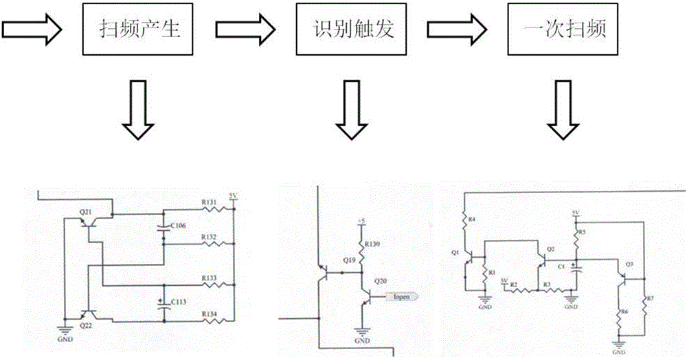
[0027] A start-up and control circuit of an electronic ballast for a gas discharge lamp, the start-up and control circuit includes a frequency sweep generating circuit I, an identification trigger circuit II, a primary frequency sweep circuit III and an enabling circuit IV;

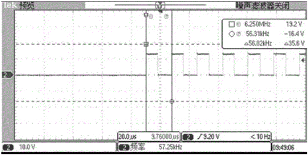
[0028] The frequency sweep generating circuit I is used to generate a PWM wave whose frequency changes from high to low; the input end of the frequency sweep generating circuit I is connected to the control voltage, and the output end of the frequency sweep generating circuit I is connected to the input end of the identification trigger circuit II;

[0029] The identification trigger circuit II is used to eliminate the potential safety hazard of the ballast during normal operation by changing the circuit working state after sweeping the frequency to the resonance point and triggeri...


PUM


Abstract

The invention discloses a start and control circuit of a gas discharge lamp electronic ballast. The circuit comprises a frequency sweep generation circuit, an identification trigger circuit, a primary frequency sweep circuit and an enable circuit, wherein the frequency sweep generation circuit is used for generating a PWM wave of which the frequency is changed from high to low; the identification trigger circuit is used for carrying out frequency sweep to a resonance point and triggering a lamp tube, and then eliminating a potential safety hazard when the ballast normally works through modifying resonance parameters; and the primary frequency sweep circuit is used for carrying out primary frequency sweep through the PWM wave to eliminate the potential safety hazard of the ballast in a special state when the ballast is in a non-load or an overload at first. The PWM wave of triggering the lamp tube is lightened through the frequency sweep generation circuit; the frequency sweep generation circuit is cut off through the identification trigger circuit; the potential safety hazard can be reduced through modifying the resonance parameters; and the potential safety hazard that the ballast is in the non-load or the overload at first is eliminated through the primary frequency sweep circuit. An analog circuit disclosed by the invention is simple in structure and low in cost and has practical value.

Description

technical field [0001] The invention relates to the technical field of ballast circuits, in particular to a start-up and control circuit of an electronic ballast for a gas discharge lamp. Background technique [0002] High-pressure gas discharge lamps are favored in green lighting projects because of their high luminous efficiency, long life and good color rendering, and the matching electronic ballasts for high-intensity gas discharge lamps have therefore become a hot spot for application. An essential feature of electronic ballasts for high-intensity gas discharge lamps is that they can provide high-voltage triggers for high-intensity gas discharge lamps, and the main implementation methods often use resonance triggering, but the high-intensity gas There will be certain safety hazards after the electronic ballast of the discharge lamp is powered on, so the resonance trigger often requires the use of frequency sweep control. The frequency sweeping function can be realized ...

Claims


Application Information

Patent Timeline
Patent Type & Authority Applications(China)
IPC IPC(8): H05B41/285
CPCH05B41/2853
Inventor 陈敏孙茂松
Owner ZHEJIANG UNIV
Learn More