
Transformer capable of increasing impedance

A technology of transformers and main transformers, applied in the field of transformers, can solve problems such as large capacity, unusable system disassembly, and high cost

Active Publication Date: 2016-10-26
孙崇山
View PDF7 Cites 2 Cited by
  • Summary
  • Abstract
  • Description
  • Claims
  • Application Information

AI Technical Summary

Problems solved by technology

The second is to use the structure of installing a reactor on the transformer (the so-called built-in reactor) to achieve the purpose of increasing the inlet reactance of the transformer, but because the cost of the reactor connected in series is sometimes extremely high, it is rarely used at present
[0006] Therefore, at this stage, there is an urgent need for a transformer that can increase the impedance without splitting the winding to overcome the stray loss caused by the split winding, the sharp rise in temperature rise, local overheating and the increased cost of the transformer
[0007] The second is to use the structure of installing a reactor on the transformer (the so-called built-in reactor scheme) to achieve the purpose of increasing the inlet reactance of the transformer. The design of the built-in reactor technology is generally connected in series on the high-voltage or low-voltage winding of the double-winding transformer Reactor, but the reactor has high voltage, large capacity, high cost and complex insulation
[0009] At this stage, the disadvantages of using high-impedance power transformers with built-in reactors are: First, because the current transformers basically adopt a single-body transformer solution, the reactor has large capacity, high voltage, and complex insulation. In most cases, it is necessary to use expensive Air core reactor
[0021] In the original power system, there is a method of transient impedance, which is to increase or decrease the number of turns of the voltage regulating winding of the transformer through the AC voltage regulating electronic switch, and adjust the impedance through the increase or decrease of the transformer voltage. The biggest disadvantage is that when adjusting the impedance , the output voltage of the transformer has changed. If the system voltage drops below 60%, the system may be disintegrated and unusable. Now there is an urgent need for a method that can change the impedance without adjusting the voltage.

Method used


Image

  • Transformer capable of increasing impedance
  • Transformer capable of increasing impedance
  • Transformer capable of increasing impedance

Examples


example

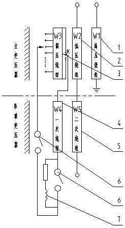
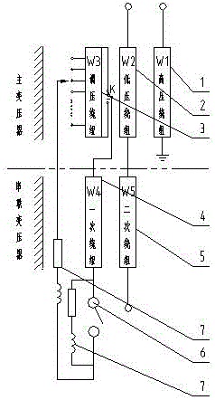
[0077] Example: SSFZ—50000 / 121 power transformer, high voltage 121±8×1.25%, medium voltage 36.75±2×2.5%, low voltage 10.5KV, oil-immersed and air-cooled, other parameters are based on GB / T 6451.

[0078] The original design as Figure ten As shown in VII, this scheme uses copper 14556KG, silicon steel sheet 24640KG, no-load loss: 35KW, load loss: 228KW. And during operation, an air-core reactor needs to be connected in series on the medium-voltage side, and an iron-core reactor should be connected in series on the low-voltage side.

[0079] A transformer that can increase the impedance adopts Figure ten Eight principles. This scheme uses copper 12145KG, silicon steel sheet 25468KG, no-load loss: 34.4KW load loss: 217KW. During operation, a core reactor is connected in series on the voltage regulating side.

[0080] When the copper price is 50 yuan / KG and the silicon steel sheet is 24 yuan / KG, the new scheme saves 7.7% of the cost compared with the original design scheme, ...


PUM


Abstract

The invention provides a transformer capable of increasing impedance. The transformer comprises a main transformer part, an in-series transformer part, a switch and an electric reactor, wherein the electric reactor and the switch are taken as an impedance regulator; when the transformer needs the small impedance, the switch is flipped down, and the electric reactor is disconnected; when the transformer needs the large impedance, the switch is flipped up, the electric reactor is in an in-series connection with the transformer, and the impedance of the transformer increases; and if the electric reactor is controllable, the impedance of the transformer can be adjusted at will. The design will become a revolutionary change in high-voltage and ultra-high voltage power transmission systems. The transformer has the advantages that system safety is greatly enhanced, and system cost is reduced; and current limiting, current stabilization, filtering, damping and the like of the system will become controllable. The transformer can be applied to high-voltage, extra high-voltage and ultrahigh-voltage AC and DC power transmission as well as other electric power systems in need of the current limiting, current stabilization, filtering and damping.

Description

technical field [0001] The invention is a transformer, which is applied in resistive, resistive-inductive and resistive-capacitive power systems. The scope of application covers such as industrial and agricultural production, scientific experiments, power transmission and various power systems. Background technique [0002] In order to ensure the reliability of system operation and limit its short-circuit current, an effective measure is to increase the short-circuit impedance of the transformer. This is why many developed countries in the world have already tended to adopt high-impedance transformers. [0003] The power system with improved transformer impedance has the following characteristics: (1) When a short-circuit accident occurs in the power grid, the short-circuit current passing through the high-impedance transformer and other power equipment is small, and the corresponding short-circuit electromagnetic force and current thermal effect will also be reduced. This...

Claims


Application Information

Patent Timeline
Patent Type & Authority Applications(China)
IPC IPC(8): H01F27/40H01F38/16H01F29/02H01F27/28
CPCH01F27/28H01F27/40H01F29/02H01F38/16
Inventor 孙崇山
Owner 孙崇山
Learn More