
Touch display panel

A touch display panel, touch technology, applied in the fields of instruments, computing, electrical and digital data processing, etc., can solve the problems of rising prices, spending more time to adjust the machine, limited wiring space, etc., to reduce production costs, The effect of reducing the adjustment and testing time and increasing the wiring space

Active Publication Date: 2016-10-26
KUSN INFOVISION OPTOELECTRONICS
View PDF5 Cites 12 Cited by
  • Summary
  • Abstract
  • Description
  • Claims
  • Application Information

AI Technical Summary

Problems solved by technology

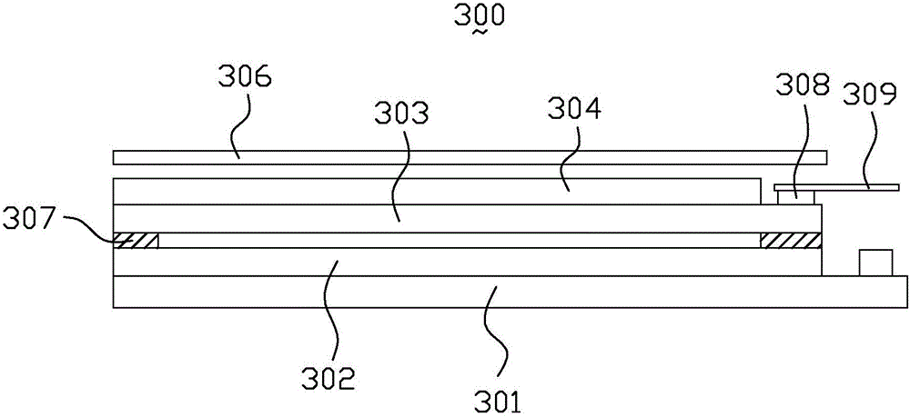
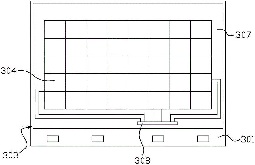
[0005] However, the wiring area of ​​the oblique wiring is concentrated in the area where the black matrix 307 is located on the periphery of the color filter substrate 303, so that the wiring space is relatively limited; , the method of lighting above the microscope can only be used to observe whether the indentation of the touch flexible circuit board connection is clear to judge the lamination effect. requirements, so the price of the touch flexible circuit board 309 will also increase accordingly, and it will take more time to adjust the machine

Method used


Image

  • Touch display panel
  • Touch display panel
  • Touch display panel

Examples


Embodiment Construction

[0022] In order to make the purpose, technical solution and advantages of the present invention clearer, the embodiments of the present invention will be further described in detail below in conjunction with the accompanying drawings.

[0023] The orientations “up” and “down” mentioned in the description of the present invention are only used to represent the relative orientation relationship; for the drawings in this specification, the upper part of the touch display panel 10 is closer to the viewer, while the lower part is closer to the viewer. away from viewers.

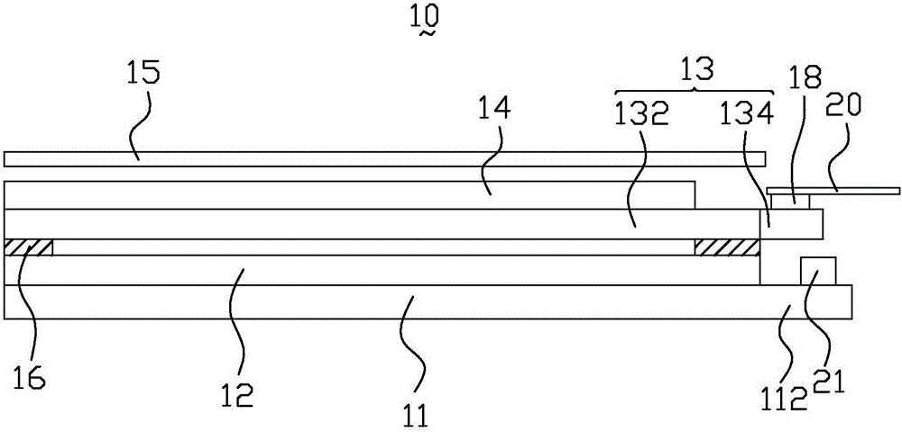
[0024] image 3 is a schematic cross-sectional structure diagram of the touch display panel in the embodiment of the present invention. Specifically, see image 3 , the touch display panel 10 of the present invention includes a TFT substrate 11, a liquid crystal layer 12, a CF substrate 13, a touch sensing layer 14, and a protective cover 15 from bottom to top. or functional requirements to insert other additio...


PUM


Abstract

The invention provides a touch display panel which sequentially comprises a TFT (Thin-Film Transistor) substrate, a liquid crystal layer, a special-shaped CF (Color Filter) substrate and a touch sensor from bottom to top. The CF substrate comprises a rectangular CF mainboard region and at least one CF externally expanded region; a black matrix of a certain width is arranged on the periphery of the CF mainboard region; the CF externally expanded regions are convexly arranged at one side of the CF mainboard region and above a terminal region of the TFT substrate; a touch flexible circuit board bonding region is arranged on one CF externally expanded region; the touch sensor is led to the touch flexible circuit board bonding region by routing of inclined wires in the black matrix region; and then the touch flexible circuit board bonding region is electrically connected with a touch flexible circuit board. According to the touch display panel, due to arrangement of the CF externally expanded regions and increase of an available space, the touch flexible circuit board bonding region is arranged in the CF externally expanded regions and a routing space of the inclined wires in the black matrix region is increased; and meanwhile, the requirements of the touch flexible circuit board are weakened, and cost of the touch flexible circuit board is reduced.

Description

technical field [0001] The present invention relates to the technical field of touch display, in particular to a touch display panel. Background technique [0002] With the development of the information age and the acceleration of the pace of life, touch technology has gradually replaced the traditional mouse and keyboard due to its humanized design and simple and fast input, and is widely used in various electronic products. Among them, the capacitive touch screen is widely used due to its advantages of fast response, high sensitivity, good reliability and high durability. The capacitive touch screen mainly includes a protective cover (Cover Lens) and a touch sensing layer (Touch Sensor). The sensing principle is to apply a voltage to the four corners of the sensing area of ​​the screen and form a fixed electric field. The capacitance change between the human body and the transparent electrode can cause the electric field to induce a current, which can be measured by the ...

Claims


Application Information

Patent Timeline
Patent Type & Authority Applications(China)
IPC IPC(8): G06F3/041G06F3/044
CPCG06F3/0412G06F3/044G06F2203/04103
Inventor 邱峰青王超
Owner KUSN INFOVISION OPTOELECTRONICS
Learn More