
Cassette structure capable of detecting substrate integrity and method for detecting substrate integrity

An integrity and substrate technology, applied in measuring devices, optical testing flaws/defects, instruments, etc., can solve problems that affect production efficiency, cannot detect substrate cracks, consume a lot of time, and manually clean debris to avoid production Effects of threats to efficiency and production safety

Active Publication Date: 2019-06-28
GUANGZHOU GOVISIONOX TECH CO LTD
View PDF6 Cites 0 Cited by
  • Summary
  • Abstract
  • Description
  • Claims
  • Application Information

AI Technical Summary

Problems solved by technology

However, in the actual production process, there may be situations where the position of the manipulator is shifted, etc., so that the substrate 20 will hit the clamp and the substrate will be broken.
Or, before the robot picks up the substrate, the substrate has been broken due to destructive external force during transportation or process
When the substrate is damaged in the lock, and the process machine cannot identify whether it is broken, after the broken substrate enters the process chamber, process risks such as debris will be generated, which will consume a lot of time and manpower to clean the debris, affecting Productivity
[0005] However, the current magazine cannot detect whether the substrate it carries is broken (that is, whether it is complete), so it is urgent to provide a cassette structure capable of detecting the integrity of the substrate and a method for detecting the integrity of the substrate, so as to Solve the above technical problems

Method used


Image

  • Cassette structure capable of detecting substrate integrity and method for detecting substrate integrity
  • Cassette structure capable of detecting substrate integrity and method for detecting substrate integrity
  • Cassette structure capable of detecting substrate integrity and method for detecting substrate integrity

Examples


Embodiment 1

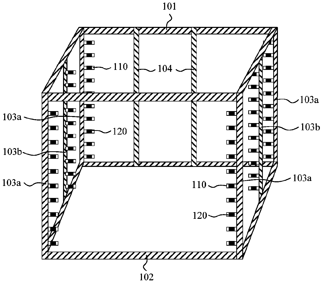
[0035] In this embodiment, the detection unit is a pressure detection unit as an example for detailed description. image 3 A schematic diagram of the cassette structure provided in this embodiment, Figure 4 for image 3 The card gate structure shown is the front view of the carrier substrate. Such as image 3 with Figure 4 As shown, the cassette structure includes an outer frame, a supporting member 110, a pressure detection unit 120, and a signal processing unit (not shown in the figure). The supporting members 110 are arranged at intervals on two opposite sides inside the outer frame, and the supporting members 110 are arranged in layers to define a plurality of accommodating spaces 110', thereby supporting the substrate 200. The pressure detecting unit 120 is disposed on the surface of the supporting member 110 carrying the substrate, and generates a pressure sensing signal indicating the integrity of the substrate. The signal processing unit is connected to the pressure ...

Embodiment 2

[0049] In this embodiment, the detection unit is an optical detection unit as an example for detailed description. Picture 12 A schematic diagram of the cassette structure provided in this embodiment, Figure 13 for Picture 12 The card gate structure shown is the front view of the carrier substrate. Such as Picture 12 with Figure 13 As shown, the cassette structure includes an outer frame, a supporting member 110, an optical detection unit 130, and a signal processing unit (not shown in the figure). The supporting members 110 are arranged at intervals on two opposite sides inside the outer frame, and the supporting members 110 are arranged in layers to define a plurality of accommodating spaces 110', so as to accommodate and support the substrate 200. The optical detection unit 130 is disposed on the supporting member 110 and located on two opposite sides of the accommodating space 110' to generate a light intensity sensing signal indicating the integrity of the substrate. ...

Embodiment 3

[0059] In this embodiment, the detection unit includes both a pressure detection unit and an optical detection unit as an example for detailed description. Figure 14 It is a front view of the cassette carrier substrate provided by this embodiment. Such as Figure 14 As shown, the cassette structure includes an outer frame, a supporting member 110, a pressure detection unit 120, an optical detection unit 130, and a signal processing unit (not shown in the figure). The pressure detecting unit 120 is disposed on the surface of the supporting member 110 carrying the substrate, and generates a pressure sensing signal indicating the integrity of the substrate. The signal processing unit is connected to the pressure detection unit 120 to receive the pressure sensing signal and process the pressure sensing signal. The optical detection unit 130 is arranged on the supporting member 110 and located on two opposite surfaces of the accommodating space 110', and generates a light intensity...


PUM


Abstract

The invention provides a cartridge structure capable of sensing the completeness of a substrate and a method for sensing the completeness of the substrate. The cartridge structure capable of sensing the completeness of the substrate comprises an outer frame, supporting parts, a sensing unit and a signal processing unit, wherein the supporting parts are arranged on the outer frame at intervals to define an accommodating space for carrying the substrate, the sensing unit is arranged on at least partial supporting parts and generates a sensing signal indicating the completeness of the substrate, the signal processing unit is connected with the sensing unit and processes the sensing signal so as to detect the completeness of the substrate in the cartridge structure, so that the incomplete substrate can be effectively prevented from entering a next step not to threaten the production efficiency and the production safety.

Description

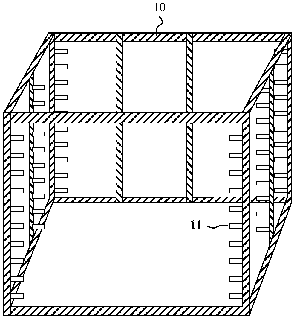
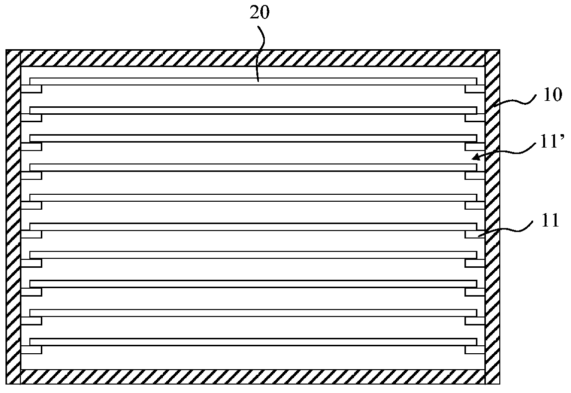
Technical field [0001] The invention relates to the field of display technology, and in particular to a cassette structure capable of detecting the integrity of a substrate and a method for detecting the integrity of the substrate. Background technique [0002] In the production process of the display panel, due to the complicated process and numerous steps, the glass substrate as the substrate needs to go back and forth between relatively independent production equipment many times. In actual production, a cassette capable of carrying multiple substrates is usually used as a carrying device for storing and transporting substrates. [0003] figure 1 Is a schematic diagram of the structure of a cassette in the prior art, figure 2 for figure 1 The front view of the card gate carrier substrate shown, such as figure 1 with figure 2 As shown, the outer frame 10 of the cassette structure is provided with a plurality of supporting members 11 arranged at intervals on opposite sides of th...

Claims


Application Information

Patent Timeline
Patent Type & Authority Patents(China)
IPC IPC(8): G01N21/88G01N33/00
CPCG01N21/88G01N33/00
Inventor 谭朋利
Owner GUANGZHOU GOVISIONOX TECH CO LTD
Learn More