Rotary machine holographic diagnostics method based on frequency modulation information reconstruction

A technology of rotating machinery and diagnostic methods, applied in the testing of mechanical components, testing of machine/structural components, measuring devices, etc., can solve problems such as the inability to directly obtain torsional vibration signals of rotating equipment, achieve intuitive and complete diagnostic results, and improve utilization The effect of efficiency and hardware cost saving

Active Publication Date: 2016-10-26
XI AN JIAOTONG UNIV
View PDF7 Cites 6 Cited by
  • Summary
  • Abstract
  • Description
  • Claims
  • Application Information

AI Technical Summary

Problems solved by technology

Since most of the rotating equipment operating on site is not equipped with torsional vibration measurement devices, it means that the torsional vibration signal of the rotating equipment cannot be directly obtained

Method used


Image

  • Rotary machine holographic diagnostics method based on frequency modulation information reconstruction
  • Rotary machine holographic diagnostics method based on frequency modulation information reconstruction
  • Rotary machine holographic diagnostics method based on frequency modulation information reconstruction

Examples


Embodiment 1

[0051] Embodiment 1, using the dynamics simulation signal of the rotor system for verification, and establishing the finite element model of the rotor system such as figure 1 As shown, the dynamic and static rubbing fault of the rotor is caused by the unbalance of the rotor. The dynamic and static rubbing fault simulation is carried out by changing the dynamic and static spacing. The basic parameters of the finite element model of the rotor system are shown in Table 1.

[0052] Table 1 Basic parameter table of the finite element model of the rotor system

[0053]

[0054] The element stiffness matrix, element mass matrix, and element gyro force matrix of the rotor system are as follows:

[0055] The element stiffness matrix is:

[0056] [ M e ] = E A l ...

Embodiment 2

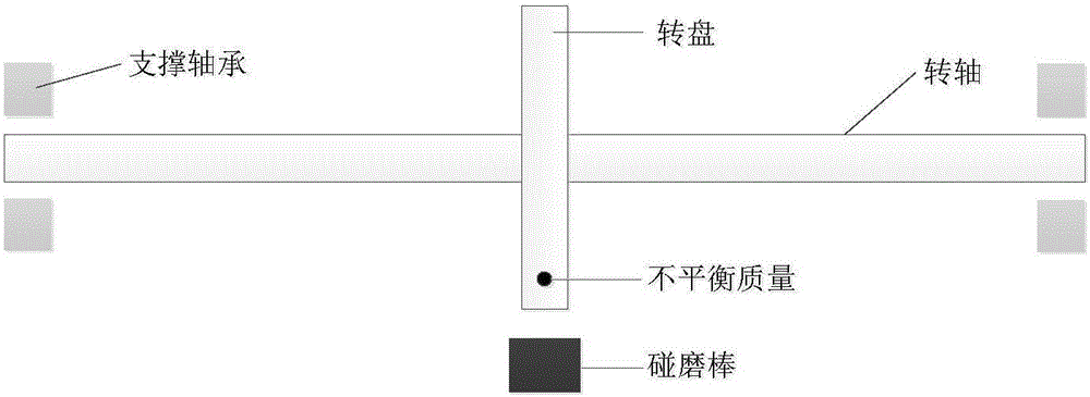
[0089] Example 2, through the Bentley RK4 rotor test bench for experimental verification, the structure diagram of the Bentley RK4 rotor test bench is as follows Figure 4 As shown, the diameter of the rotor is 10mm, the length is 550mm, and the front and rear support span is 325mm. Viewed from the drive end, the rotor system rotates in the counterclockwise direction, and two balancers for adding balance mass are arranged axially symmetrically in the rotor span. Disk, each disk weighs 0.8kg, 16 holes are equiangularly distributed along the circumference of the balance disk at a radius of 30mm for adding balance mass, the experiment simulates the dynamic and static friction fault of the rotor by adjusting the distance between the friction rod and the rotor, the experiment The rev is set at 1700rpm.

[0090] A method for holographic diagnosis of rotating machinery based on frequency modulation information reconstruction, comprising the following steps:

[0091] Step 1: Install ...


PUM


Abstract

The present invention relates to a rotary machine holographic diagnostics method based on frequency modulation information reconstruction. The method is characterized by firstly installing two displacement sensors of which the included angle is 90 degrees on a rotor vibration test cross-section, acquiring the displacement vibration signals in the X and Y directions, carrying out the ensemble empirical mode decomposition (EEMD) on the displacement vibration signals, obtaining a plurality of intrinsic mode functions (IMF), then carrying out the spectral analysis on the IMFs, and selecting the IMF<x>(t) and the IMF<y>(t) which contain a rotating frequency; adopting a direct orthogonal method to calculate the instantaneous frequencies IF<x>(t) and the IF<y>(t) of the IMF<x>(t) and the IMF<y>(t) respectively, extracting the frequency, amplitude and phase information of the instantaneous frequencies IF<x>(t) and the IF<y>(t) to synthesize a two-dimensional holospectrum, and effectively identifying the operation state of a rotor. The rotary machine holographic diagnostics method based on frequency modulation information reconstruction of the present invention comprehensively considers the vibration signals of the rotor in the horizontal and vertical directions, fully utilizes the phase information, fuses the frequency, amplitude and phase information of the signals organically, and is visual and complete in diagnosis result.

Description

technical field [0001] The invention relates to the technical field of fault diagnosis of rotating machinery, in particular to a holographic diagnosis method of rotating machinery based on reconstruction of frequency modulation information. Background technique [0002] Large rotating machinery is the key equipment in many industries such as petroleum, chemical industry, energy and metallurgy, among which the rotor assembly is the core of the rotating machinery. The common faults of rotors include unbalance, dynamic and static rubbing, oil film whirl, etc. Among them, the vibration caused by rotor dynamic and static rubbing faults often shows nonlinear characteristics, which is a kind of fault form that is difficult to diagnose. Some existing signal analysis methods are often unable to accurately and intuitively judge the operating state of the rotor, especially for the diagnosis of early weak faults. [0003] The vibration caused by the dynamic and static friction of the r...

Claims


Application Information

Patent Timeline
Patent Type & Authority Applications(China)
IPC IPC(8): G01M13/00
CPCG01M13/00
Inventor 王琇峰郭美娜曾志豪林京雷亚国赵明
Owner XI AN JIAOTONG UNIV
Why Eureka
Try Eureka