
Indoor robot SLAM method and system

An indoor robot and robot technology, applied in the direction of instruments, measuring devices, surveying and navigation, etc., can solve the problems of not being the best choice and the absence of SLAM methods, etc., to achieve small appearance structure restrictions, high real-time performance, and small amount of calculation Effect

Active Publication Date: 2016-10-26
青岛克路德智能科技有限公司
View PDF11 Cites 72 Cited by
  • Summary
  • Abstract
  • Description
  • Claims
  • Application Information

AI Technical Summary

Problems solved by technology

[0004] However, limited by the cost of sensors, installation structure, algorithm efficiency and accuracy, there are basically no SLAM methods that can be commercialized.
For indoor robots, considering the actual usage scenarios, laser rangefinders must not be the best choice for indoor robots for SLAM due to factors such as price, noise, and structure.

Method used


Image

  • Indoor robot SLAM method and system
  • Indoor robot SLAM method and system
  • Indoor robot SLAM method and system

Examples


Embodiment 1

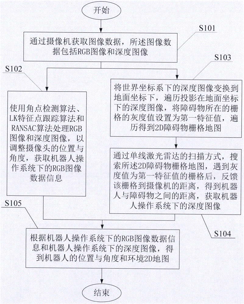
[0066] like figure 1 As shown, a SLAM method for an indoor robot is disclosed in this embodiment, and the method includes:

[0067] S101. Obtain image data through a camera, where the image data includes an RGB image and a depth image;

[0068] S102, use the corner point detection algorithm, the LK feature point tracking algorithm and the RANSAC algorithm to process the RGB image and the depth image, to adjust the position and angle of the camera, and obtain the RGB image data information under the robot operating system;

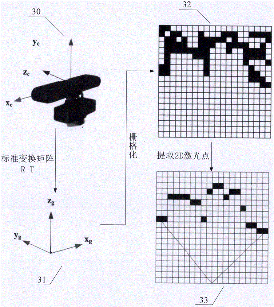
[0069] S103. Transform the depth image in the world coordinate system to the ground coordinate, traverse the depth image projected in the ground coordinate, set the gray value of the grid where the obstacle is located as the first eigenvalue, and traverse to obtain a 2D obstacle grid grid map;

[0070] S104. Search the 2D obstacle grid map through the single-line laser radar scanning method, and when encountering a grid whose gray value is the first eigen...

Embodiment 2

[0098] like Figure 4 As shown, the present invention also discloses a SLAM system for an indoor robot, the system comprising:

[0099] An acquisition module 201, configured to acquire image data through a camera, the image data comprising an RGB image and a depth image;

[0100] The RGB image processing module 202 is used to process RGB images and depth images using corner detection algorithm, LK feature point tracking algorithm and RANSAC algorithm to adjust the position and angle of the camera and obtain RGB image data information under the robot operating system;

[0101] The grid module 203 is used to transform the depth image in the world coordinate system to the ground coordinate, traverse the depth image projected in the ground coordinate, set the gray value of the grid where the obstacle is located as the first eigenvalue, and traverse Get a 2D obstacle grid map;

[0102] The depth image processing module 204 is configured to search the 2D obstacle grid map through ...


PUM


Abstract

The invention discloses an indoor robot SLAM method. The method comprises the following steps: obtaining image data through a camera, wherein the image data comprises RGB images and depth images; using a corner detection algorithm, an LK characteristic point tracing algorithm, and a RANSAC algorithm to process the RGB images and depth images to adjust the position and angle of the camera so as to obtain the RGB image data information under a robot operation system; converting the depth images in a world coordinate system to a ground coordinate, traversing the depth images that are projected on the ground coordinate, setting the gray value of the grid where a barrier stays as a first characteristic value, carrying out traversing to obtain a 2D barrier grid map; through a single line laser radar scanning mode, searching the 2D barrier grid map, when the grid with a grey value equal to the first characteristic value is found, feeding back the distance between the grid and the camera to obtain the distance between a robot and the barrier, obtaining the depth images under a robot operation system, and obtaining an environment 2D map.

Description

technical field [0001] The present invention relates to the technical field of indoor autonomous navigation of robots, and more specifically, relates to a SLAM method and system for indoor robots. Background technique [0002] In the related research on intelligent navigation technology of autonomous mobile robots, the simultaneous localization and map construction (SLAM, SLAM, for short) technology of robots in unknown environments is a key technology, which has both application and academic value. It has become a research hotspot in this field in the past two decades. Under this trend, scholars have proposed a variety of methods to solve the SLAM problem, and also applied a variety of sensors to solve the environmental perception problem in SLAM. [0003] The first problem to be solved by SLAM technology is to select an appropriate sensor system to perceive the environment in which the robot is located. Such as laser range finder, sonar, visual sensor, GPS, compass and o...

Claims


Application Information

Patent Timeline
Patent Type & Authority Applications(China)
IPC IPC(8): G01C21/00G01C21/20
CPCG01C21/00G01C21/206
Inventor 王运志
Owner 青岛克路德智能科技有限公司
Learn More