Parallel combining connecting part end cover closing structure of loop type heat pipe

A technology of closed structure and group connection, which is applied to indirect heat exchangers, lighting and heating equipment, etc., and can solve the problems of reduced heat dissipation efficiency, complex structure and high manufacturing cost, etc.

Inactive Publication Date: 2016-10-26
SUZHOU FORCECON ELECTRIC
View PDF8 Cites 2 Cited by
  • Summary
  • Abstract
  • Description
  • Claims
  • Application Information

AI Technical Summary

Problems solved by technology

[0002] In view of the internal structure design of the early heat pipe, the steam flow path and the condensate flow path were arranged in the same pipe section space and were arranged in an overlapping state, so that the flow directions conflicted with each other and hindered each other, resulting in reduced heat dissipation efficiency and other problems. The industry has developed a loop-type heat pipe structure. In this heat pipe structure, the steam flow path and the condensate flow path are set in different sections in the heat pipe space, and the overall form of a loop form can solve the aforementioned problems.
[0003] However, the existing loop-type heat pipe structure that can be seen at present still has its shortcomings. The two ends are spaced apart from each other, and a base is set between the two ends. The base is provided with a connecting channel, and the two ends of the pipe body must be provided with through holes in advance to communicate with the connecting channel. In this way, the ring-shaped loop space form inside the existing loop-type heat pipe can be formed; however, this type of existing loop-type heat pipe shape is still found in the practical application experience of the industry, because the base must be separately manufactured and processed. Moreover, the pipe walls at both ends of the pipe body must also be drilled through secondary processing to form radial through holes, and then the alignment and assembly work between the base and the two ends of the pipe body must be performed, so overall there is still The structural composition is too complicated, the manufacturing process is difficult, and the manufacturing cost is too high and does not meet the best industrial economic benefits. It is necessary to improve and break through.

Method used


Image

  • Parallel combining connecting part end cover closing structure of loop type heat pipe
  • Parallel combining connecting part end cover closing structure of loop type heat pipe
  • Parallel combining connecting part end cover closing structure of loop type heat pipe

Examples


Embodiment

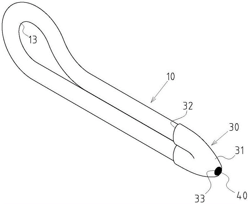
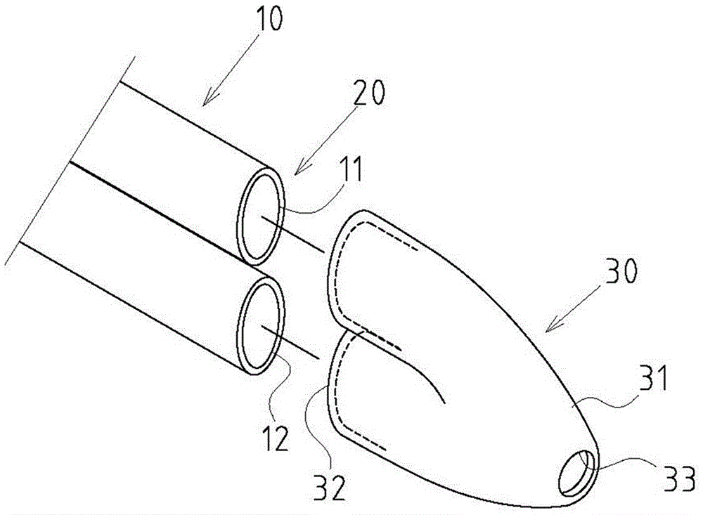
[0027] Example: see Figure 1~5 Shown is a preferred embodiment of the end cap closure structure of the parallel connection part of the loop heat pipe of the present invention, but these embodiments are for illustration purposes only, and are not limited by this structure in the patent application.

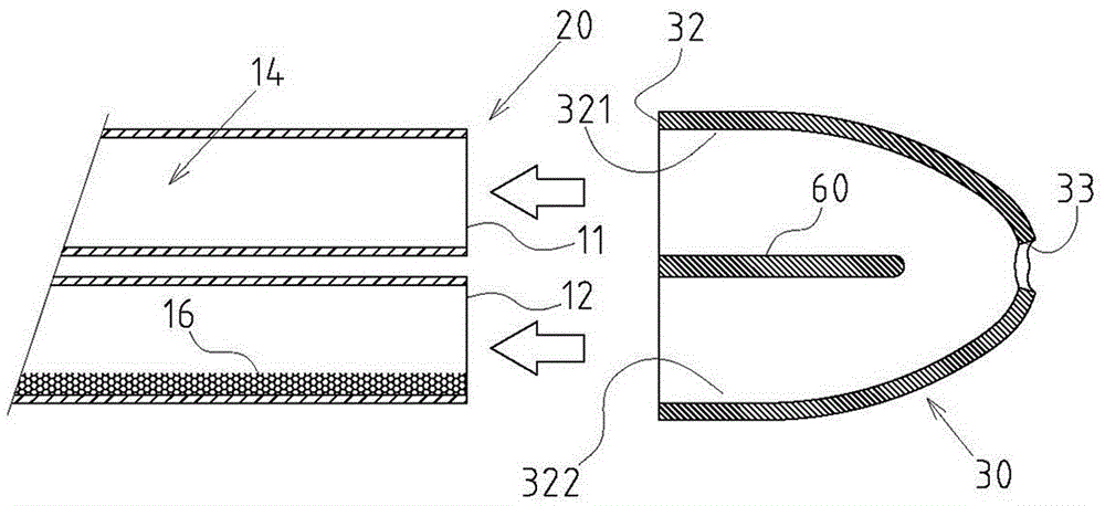
[0028] The closure structure of the end cover of the parallel connection part of the loop type heat pipe includes the following components:

[0029] A hollow tube body 10 is bent into a folded shape and includes two tube ports 11, 12 and a loop-type section 13 between the two tube ports 11, 12, and the hollow tube body 10 has a flow channel inside Space 14, the channel space 14 includes an evaporation section 141 and a condensation section 142 (only marked in Figure 5 ) and accommodate a working fluid 15; and at least the evaporating section 141 is provided with a capillary 16; a group of connecting parts 20, the two tube ports 11, 12 passing through the hollow tube body 10 are ...


PUM


Abstract

A parallel combining connecting part end cover closing structure of a loop type heat pipe is characterized by mainly comprising a hollow pipe body, a parallel combining connecting part and a closing end cover, wherein the hollow pipe body is bent into an inflection state and comprises two pipe end openings and a loop type section, inner runner space of the hollow pipe body comprises an evaporation section and a condensation section and contains working fluid, and at least the evaporation section is provided with a capillary structure; the parallel combining connecting part is formed in the state that the two pipe end openings of the hollow pipe body are the same in direction, and main pipe bodies are arranged in parallel; and the closing end cover is in a cap cover form and comprises a closing end and a sleeving and combining end, the sleeving and combining end comprises at least one sleeving opening so as to conduct sleeving and combining on the two pipe end openings of the parallel combining connecting part in an airtight state, the closing end is provided with an air removing hole, and after finishing the vacuum pumping and air removing state in the inner runner space in the hollow pipe body, the air removing hole is closed into a closed state. The parallel combining connecting part end cover closing structure has practical advancement that manufacturing, machining and forming are easier, and the manufacturing cost is reduced, and the good airtight effect is integrated and also has good industrial economic benefits.

Description

technical field [0001] The invention relates to a loop-type heat pipe, in particular to an innovative end-cap-type closed structure of the parallel connection part of the loop-type heat pipe. Background technique [0002] In view of the internal structure design of the early heat pipe, the steam flow path and the condensate flow path were arranged in the same pipe section space and were arranged in an overlapping state, so that the flow directions conflicted with each other and hindered each other, resulting in reduced heat dissipation efficiency and other problems. The industry has developed a loop-type heat pipe structure. In this heat pipe structure, the steam flow path and the condensate flow path are set in different sections in the heat pipe space, and form a loop form as a whole, so as to solve the aforementioned problems. [0003] However, the existing loop-type heat pipe structure that can be seen at present still has its shortcomings. The two ends are spaced apart...

Claims


Application Information

Patent Timeline
Patent Type & Authority Applications(China)
IPC IPC(8): F28D15/04
CPCF28D15/043
Inventor 何信威黄志仁叶肇浩
Owner SUZHOU FORCECON ELECTRIC
Why Eureka
Try Eureka