
High-speed train gearbox shaft sealing structure

A high-speed train and shaft sealing technology, which is applied in the direction of engine sealing, engine components, mechanical equipment, etc., can solve the problems that cannot meet the shaft sealing requirements of high-speed train gearboxes, and achieve the advantages of ingenious structure, reliable sealing effect and guaranteed reliability Effect

Inactive Publication Date: 2016-10-26
ZHENGZHOU RES INST OF MECHANICAL ENG CO LTD
View PDF8 Cites 3 Cited by
  • Summary
  • Abstract
  • Description
  • Claims
  • Application Information

AI Technical Summary

Problems solved by technology

The above two shaft sealing devices only improve or optimize the sealing structure inside the gearbox. Although they can improve the sealing capacity to a certain extent, they still cannot meet the shaft sealing requirements of high-speed train gearboxes.

Method used


Image

  • High-speed train gearbox shaft sealing structure
  • High-speed train gearbox shaft sealing structure
  • High-speed train gearbox shaft sealing structure

Examples


Embodiment Construction

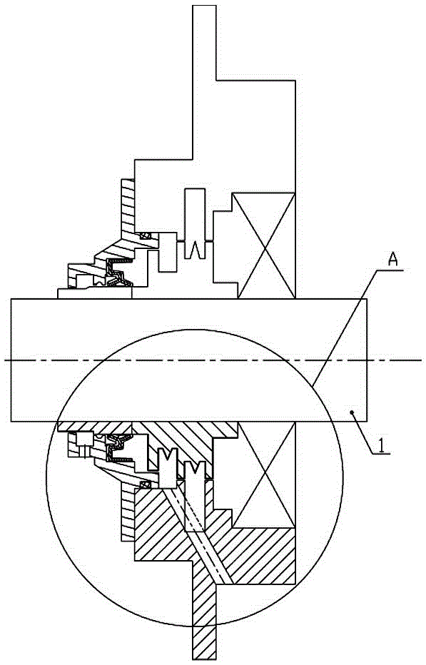
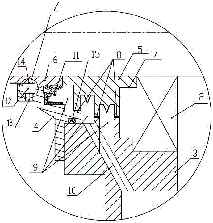
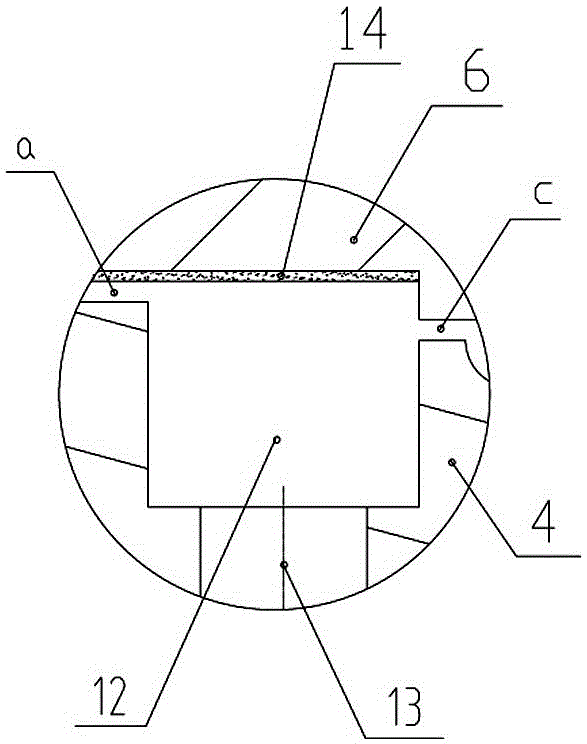
[0019] Such as figure 1 , 2 , 3, the high-speed train gearbox shaft sealing structure of the present invention includes a rotating shaft 1, and the rotating shaft 1 is arranged on the gear case body 3 through the bearing 2, and the end portion of the rotating shaft is arranged on the outside of the gear case body 3 The extended end cover 4 is provided with an O-ring seal 15 on the joint surface of the end cover 4 and the gear case 3; a shaft sealing device is provided on the rotating shaft between the bearing 2 and the end cover 4; in order to improve the shaft seal reliability, the shaft sealing device of the present invention includes a metal inner oil deflector ring 5 and an outer oil deflector ring 6 which are sequentially sealed and sleeved on the rotating shaft 1, the inner oil deflector ring 5 is attached to the end of the bearing 2, and the outer deflector ring 5 is attached to the end of the bearing 2. The oil ring 6 extends out of the end cover 4 along the axial sur...


PUM

PropertyMeasurementUnit
Radial sizeaaaaaaaaaa
Widthaaaaaaaaaa
Lengthaaaaaaaaaa

Abstract

The invention discloses a high-speed train gearbox shaft sealing structure. A rotating shaft is arranged on a box body through a bearing. An end cover is arranged on the outer portion of the box body. A shaft sealing device is arranged at the position, between the bearing and the end cover, of the rotating shaft. The shaft sealing device comprises an inner oil blocking ring and an outer oil blocking ring which are arranged on the rotating shaft in a sealed and sleeving manner. The outer ring face of the inner oil blocking ring is treated to form a super-oleophobic film layer, and annular gaps and annular cavities are formed among the super-oleophobic film layer, the box body and the end cover in a sequentially-staggered manner. The end cover is internally of a step type structure. A framework oil seal is arranged in an annular cavity between the outer oil blocking ring and the end cover. An annular groove is formed in the end cover, a draining hole is formed in the bottom of the end cover, and the outer ring face, corresponding to the annular groove, of the outer oil blocking ring is treated to form a super-hydrophobic film layer. The high-speed train gearbox shaft sealing structure is ingenious in structure and good in sealing effect, the outer ring face of the inner oil blocking ring is treated to form the super-oleophobic film layer so that leakage of lubricating liquid of a gearbox can be effectively reduced; and the outer ring face of the outer oil blocking ring is treated to form the super-hydrophobic film layer so that water molecules and impurities outside the box cannot enter the box body, and reliability of high-speed train gearbox shaft sealing is ensured.

Description

technical field [0001] The invention relates to a gear box shaft sealing structure, in particular to a high-speed train gear box shaft sealing structure. Background technique [0002] Gearbox lube seals are common devices in centrifugal compressors, compressors, blowers and other industrial machinery. The gear box generally adopts a labyrinth seal. During the working process, the seal is fixed and the shaft rotates to achieve a certain sealing effect. [0003] With the rapid development of my country's high-speed railways, the operating conditions of high-speed train gearboxes have become increasingly severe. Due to the high rotation speed of the transmission shaft of the conventional high-speed train gearbox, water molecules and impurities such as wind, sand, rain and snow from the outside can easily enter the inside of the box along the transmission shaft, causing contamination of the lubricating oil; at the same time, the lubricating oil in the box will also be Lubricat...

Claims


Application Information

Patent Timeline
IPC IPC(8): F16J15/16F16J15/447
CPCF16J15/16F16J15/162F16J15/447
Inventor 刘杰刘世军曹志刚徐文博郭熛
Owner ZHENGZHOU RES INST OF MECHANICAL ENG CO LTD
Learn More