Automobile suspension rack supporting base structure
A technology of automobile suspension and body, which is applied to suspensions, vehicle parts, cantilevers mounted on pivots, etc. Reduced body weight and good agility
- Summary
- Abstract
- Description
- Claims
- Application Information
AI Technical Summary
Problems solved by technology
Method used
Image
Examples
Embodiment 1
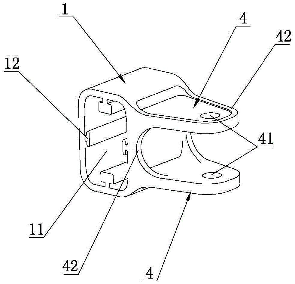
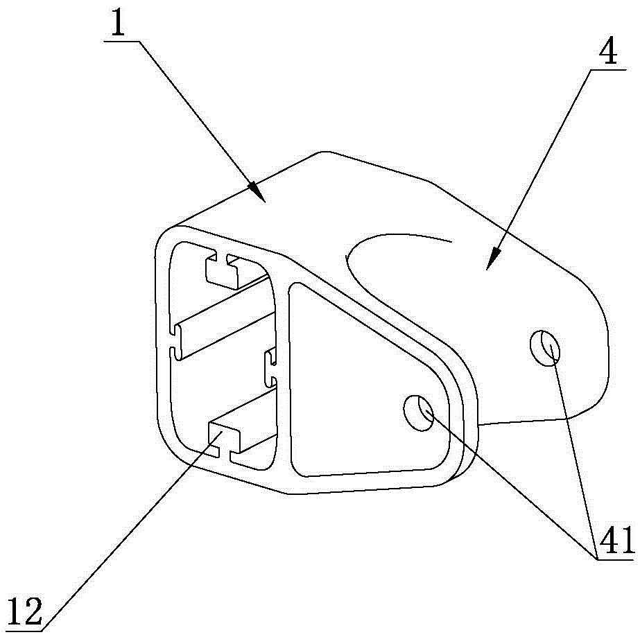
[0025] Such as figure 1 , figure 2 with Figure 4 As shown, an automobile suspension support structure of the present invention includes a bushing body 1 with a bushing hole 11 passing through its axis, and the bushing body 1 is installed and fixed through the bushing hole 11. In the profile beam 2 of the vehicle body, the sleeve body 1 is provided with a mounting lug 4 for mounting a swing member 3, the mounting lug 4 is provided with an axle hole 41, and the swing member 3 is rotatably connected to the swing member 3 through the axle hole 41 Install ear piece 4. The support structure can be directly installed and fixed to the profile beam 2 of the car body. It has the characteristics of simple and compactness, high installation and positioning accuracy, and convenient manufacturing and assembly. It is suitable for the positioning of a variety of suspension supports. By optimizing the topological structure and The size can reduce the weight of the car body. The support struct...
Embodiment 2
[0033] Such as image 3 with Figure 4 As shown, the difference between this embodiment and the first embodiment is that the axis of the shaft hole 41 of the mounting lug 4 of this embodiment is parallel to the axis of the sleeve hole 11. This embodiment is applicable to a different independent suspension or different connecting parts of the same independent suspension from the first embodiment.
[0034] The rest of the present embodiment is the same as the first embodiment, and will not be repeated here.
Embodiment 3
[0036] Such as Figure 5 with Image 6 As shown, the difference between this embodiment and the first embodiment is that the number of the T-shaped jaws is two, and the axis of the shaft hole 41 of the mounting lug 4 is parallel to the axis of the sleeve hole 11 and is coaxial The axis of the shaft hole 41 does not coincide with the axis of the rectangular sleeve hole 11, and the swing member 3 in this embodiment is a connecting rod rotation shaft. The support structure is matched with the connecting rod rotary shaft and can be used for the assembly of the rear suspension system of the automobile.
[0037] The rest of the present embodiment is the same as the first embodiment, and will not be repeated here.
[0038] Such as Figure 7 As shown, in an automobile suspension system of the present invention, the automobile suspension system 6 is connected to the automobile suspension support structure through the swing member 3. The automobile suspension system 6 inherits the technical...
PUM
 Abstract
Description
Claims
Application Information
 - R&D Engineer
- R&D Manager
- IP Professional
- Industry Leading Data Capabilities
- Powerful AI technology
- Patent DNA Extraction
Browse by: Latest US Patents, China's latest patents, Technical Efficacy Thesaurus, Application Domain, Technology Topic, Popular Technical Reports.
© 2024 PatSnap. All rights reserved.Legal|Privacy policy|Modern Slavery Act Transparency Statement|Sitemap|About US| Contact US: help@patsnap.com


