A thermal sleeve positioning device for motor test gears

A technology for positioning device and motor test, which is applied in the direction of machine gear/transmission mechanism testing, measuring device, workpiece clamping device, etc., which can solve the problems of motor shaft and test gear damage, scrapping of motor shaft and test gear, and failure to complete the test. , to achieve the effect of preventing slipping and falling off, simple and fast operation, and ensuring reliability

Active Publication Date: 2017-08-04
CHENGDU CRRC ELECTRIC MOTOR CO LTD
View PDF5 Cites 0 Cited by
  • Summary
  • Abstract
  • Description
  • Claims
  • Application Information

AI Technical Summary

Problems solved by technology

[0002] After the test gear of the existing DC / pulse current motor is heated to the specified temperature, it is directly shrunk onto the shaft of the motor, and no other restrictions or positioning measures are taken to control the insertion amount of the test gear
[0003] After practice, the existing motor test gear shrink fitting method will cause a large difference in the amount of fitting of each motor test gear
When the insertion amount is too small, the test gear will slip and fall off during the motor test, causing damage to the motor shaft and the test gear, making it impossible to complete the test, and even causing the motor shaft and the test gear to be scrapped; when the insertion amount is too large, The removal of the test gear is difficult

Method used


Image

  • A thermal sleeve positioning device for motor test gears

Examples


Embodiment

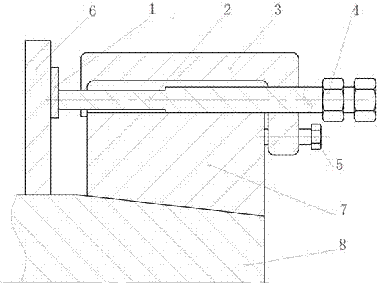
[0017] Such as figure 1 As shown, a motor test gear shrink-fit positioning device includes a sample block 1, a positioning screw 2, a positioning frame 3, a lock nut 4 and a fixing bolt 5, the positioning frame 3 is an inverted U shape, and the positioning screw 2 is from One end of the positioning frame 3 is passed to the other end, the sample block 1 is arranged at the front end of the positioning screw 2, the lock nut 4 is arranged at the rear end of the positioning frame 3, and the fixing bolt 5 is screwed into the inside from the outside at the rear end of the positioning frame 3 .

[0018] The rear end of the positioning frame 3 is higher than the front end, and the fixing bolt 5 is arranged at the rear end of the positioning frame 3 .

[0019] There are two locking nuts 4, both of which are arranged at the rear end of the spacer 3.

[0020] Working principle of the present invention:

[0021] 1. After cleaning the outer cone surface of the motor shaft 8 and the inner...


PUM


Abstract

The invention discloses a locating device for motor test gear shrinkage fit. The locating device comprises a sample block, a locating screw, a locating frame, locking nuts and a fixing bolt. The locating frame is in an inverted U shape. The locating screw is screwed into the front end from the rear end of the locating frame in a penetrating manner. The sample block is arranged at the front end of the locating screw. The locking nuts are arranged at the rear end of the locating frame. The fixing bolt is screwed into the inner side from the outer side at the rear end of the locating frame. The locating device has the beneficial effects that sample blocks with different thicknesses are selected for different types of motors, so that it is guaranteed that the shrinkage fit amount of a test gear of the same type of motor accords with the process requirement and the shrinkage fit amount of test gears of all the types of motors are almost consistent, the reliability of test gear shrinkage fit is guaranteed, and therefore the phenomena that sliding and falling off happen in the test process of the test gear or disassembly cannot be achieved easily after the test and a motor rotary shaft and the test gear are damaged or scrapped are eliminated thoroughly.

Description

technical field [0001] The invention relates to the technical field of motors, in particular to a thermal sleeve positioning device for a motor test gear. Background technique [0002] After the test gear of the existing DC / pulse current motor is heated to a specified temperature, it is directly shrunk on the rotating shaft of the motor, and no other restriction or positioning measures are taken to control the amount of the test gear inserted. [0003] After practice, the existing method of shrink fitting of motor test gears will cause a large difference in the amount of fitting of each motor test gear. When the insertion amount is too small, the test gear will slip and fall off during the motor test, causing damage to the motor shaft and the test gear, making it impossible to complete the test, and even causing the motor shaft and the test gear to be scrapped; when the insertion amount is too large, The removal of the test gear is also very difficult. [0004] Therefore, ...

Claims


Application Information

Patent Timeline
IPC IPC(8): B25B11/00G01M13/02
CPCB25B11/00G01M13/021
Inventor 李灵军林炯冷辉戚曼玲
Owner CHENGDU CRRC ELECTRIC MOTOR CO LTD
Why Eureka
Try Eureka