Underground diaphragm wall joint section steel cleaning device and cleaning method

A technique for an underground diaphragm wall and a cleaning device, which is applied in the direction of cleaning methods and appliances, cleaning methods using liquids, chemical instruments and methods, etc., and can solve the problem of affecting the connection effect of underground diaphragm wall unit sections, cleaning cohesive soil, and poor cleaning effect Ideal and other issues, to achieve the effect of simple structure, improved connection quality and low cost

Active Publication Date: 2018-02-09
CHINA COMM 2ND NAVIGATIONAL BUREAU 3RD ENG
View PDF5 Cites 0 Cited by
  • Summary
  • Abstract
  • Description
  • Claims
  • Application Information

AI Technical Summary

Problems solved by technology

Most of the existing cleaning methods use a crane to hang the wire rope brush through the wire rope sling and move it up and down several times to brush the soil in the H-shaped steel channel, because the wire rope brush cannot be close to the H-shaped steel channel to brush the soil in the deep part of the H-shaped steel Effective pressure cannot be generated, and the cleaning effect is not ideal, especially the cohesive soil in the H-shaped steel channel is difficult to clean thoroughly, which affects the connection effect between the two ends of the underground diaphragm wall under construction and the constructed underground diaphragm wall unit section , it will seriously make the enclosure fail

Method used


Image

  • Underground diaphragm wall joint section steel cleaning device and cleaning method
  • Underground diaphragm wall joint section steel cleaning device and cleaning method

Examples


Embodiment Construction

[0022] The present invention will be further described below in conjunction with drawings and embodiments.

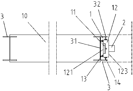
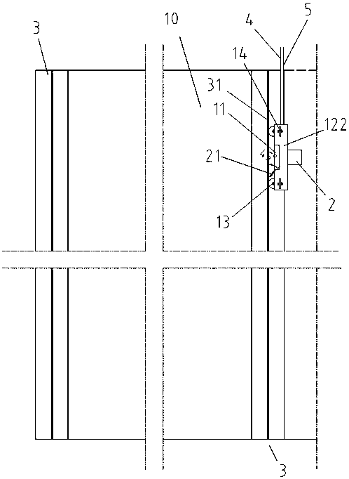
[0023] Such as figure 1 with figure 2 As shown, the device of the present invention comprises a vertical lifting trolley 1 and an underwater mud pump 2. The vertical lifting trolley 1 comprises an electromagnet 11, a vehicle body 12, 4 longitudinal wheels 13 and 4 transverse wheels 14, and the electromagnet 11 is fixed in the direction of the H On the middle part of the longitudinal bottom surface 121 of the section steel web 31, the electromagnetic attraction force of the electromagnet reaches 10-12kN, and the vertical lifting trolley 1 and the underwater mud pump 2 weighing 500 kg can be firmly erected in the notch of the H-section steel 3 , will not fall. The four longitudinal wheels 13 are divided into two rows and supported between the longitudinal bottom surface 11 of the vehicle body and the H-shaped steel web 31, and the four transverse wheels 14 are supporte...


PUM


Abstract

The invention discloses a cleaning device for underground continuous wall joint profile steel. The cleaning device comprises a vertical lifting trolley and an underwater slurry pump. The vertical lifting trolley comprises an electromagnet, a trolley body, four longitudinal trolley wheels and four transverse trolley wheels. The electromagnet is fixed to the trolley body longitudinal bottom face. The four longitudinal trolley wheels are supported between the trolley body longitudinal bottom face and a profile steel web. The four transverse trolley wheels are supported between the side faces of the two sides of the trolley body and profile steel wind plates correspondingly. A pipe orifice of a water spray pipe of the underwater slurry pump faces the profile steel web. The method comprises the following steps that (1) the magnetic vertical lifting trolley is hoisted into a profile steel notch and closely attached to the profile steel web; and (2) the underwater slurry pump sprays water to wash off soil in the profile steel notch. The device is simple in structure, convenient to use and low in cost; according to the method, soil, especially cohesive soil, in the profile steel notch can be completely cleaned up, the connecting quality of the two ends of an underground continuous wall and built unit sections of the underground continuous wall is improved, and thus the water retaining effect of an enclosure structure is ensured.

Description

technical field [0001] The invention relates to a treatment device for wall joints in the construction of an underground diaphragm wall, especially a device for removing the soil in the steel channel of the end face joint of the underground diaphragm wall, and also relates to a cleaning method using the aforementioned device, which belongs to the basic engineering construction technology field. Background technique [0002] The underground diaphragm wall is one of the foundation projects. Under the condition of the mud retaining wall, a narrow and long deep groove is excavated. After the groove is cleared, a steel cage is hung in the groove, and then the underwater concrete is poured by the conduit method to form an underground diaphragm wall. unit segment. The underground diaphragm wall unit sections are built at intervals, and a section of wall connecting the two underground diaphragm wall unit sections is built between the two sections of the underground diaphragm wall u...

Claims


Application Information

Patent Timeline
Patent Type & Authority Patents(China)
IPC IPC(8): B08B3/02E02D29/16
CPCB08B3/02E02D29/16
Inventor 刘忠友马超何源冯俭华陈鹏郭宁叶朝辉肖佳张春飞
Owner CHINA COMM 2ND NAVIGATIONAL BUREAU 3RD ENG
Why Eureka
Try Eureka